Rockwell Automation Publication PFLEX-RM003E-EN-E - January 2011 119
Detailed Drive Operation Chapter 1
Pulse Elimination
Technique (PET)
See Reflected Wave below.
Reflected Wave
Parameter 510 [FVC Mode Config], bit 9 “ReflWaveComp” enables reflected
wave compensation. The pulses from a PWM inverter using IGBTs are very short
in duration (50 ns…1 ms). These short pulse times combined with the fast rise
times (50…400 ns) of the IGBT, will result in excessive overvoltage transients at
the motor. Voltages in excess of twice the DC bus voltage (650V DC nominal at
480V input) will occur at the motor and can cause motor winding failure.
The patented reflected wave correction software in the PowerFlex 700S will
reduce these overvoltage transients from the drive to the motor. The correction
software modifies the PWM modulator to prevent PWM pulses less than a
minimum time from being applied to the motor. The minimum time between
PWM pulses is 10 microseconds. The modifications to the PWM modulator
limit the overvoltage transient to 2.25 per unit volts line-to-line peak at 600 feet
of cable.
400 V Line = 540V DC bus x 2.25 = 1215V
480 V Line = 650V DC bus x 2.25 = 1463V
600 V Line = 810V DC bus x 2.25 = 1823V
The software is standard and requires no special parameters or settings.
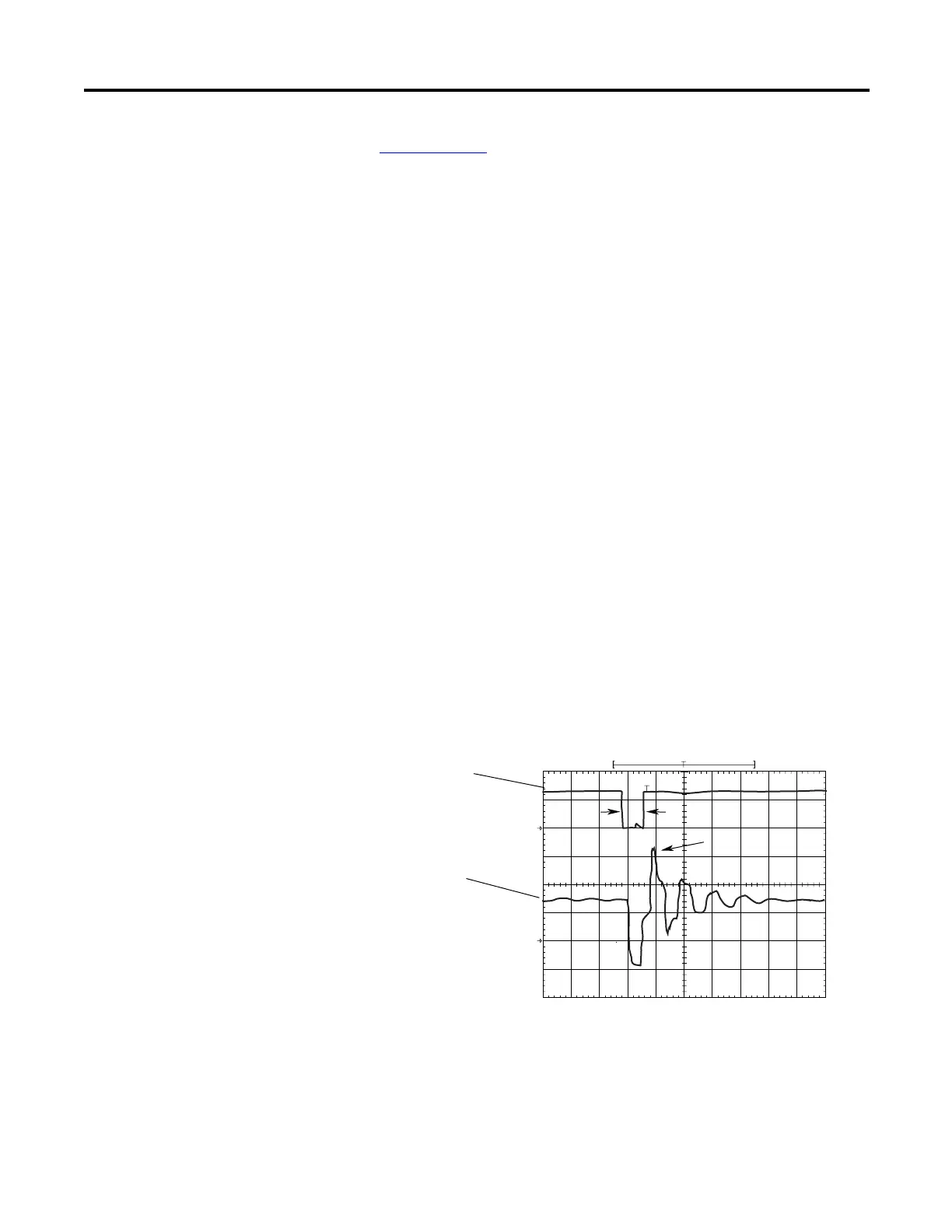
The figure below shows the inverter line-to-line output voltage (top trace) and
the motor line-to-line voltage (bottom trace) for a 10 Hp, 460V AC inverter, and
an unloaded 10 Hp AC induction motor at 60 Hz operation. 500 ft of #12 AWG
cable connects the drive to the motor.
Initially, the cable is in a fully charged condition. A transient disturbance occurs
by discharging the cable for approximately 4 ms. The propagation delay between
the inverter terminals and motor terminals is approximately 1 ms. The small time
between pulses of 4 ms does not provide sufficient time to allow the decay of the
<T
α
1670 V
pk
5010152025
Time (sec)
30 35 40 45 50
500
V/div
0
500
V/div
Inverte
Motor
0
Inverter Line-to-Line
Output Voltage
Motor Line-to-Line
Voltage
 Loading...


