120 Rockwell Automation Publication PFLEX-RM003E-EN-E - January 2011
Chapter 1 Detailed Drive Operation
cable transient. Thus, the second pulse arrives at a point in the motor terminal
voltage's natural response and excites a motor overvoltage transient greater than 2
p.u. The amplitude of the double-pulsed motor overvoltage is determined by a
number of variables. These include the damping characteristics of the cable, bus
voltage, and the time between pulses, the carrier frequency, modulation
technique, and duty cycle.
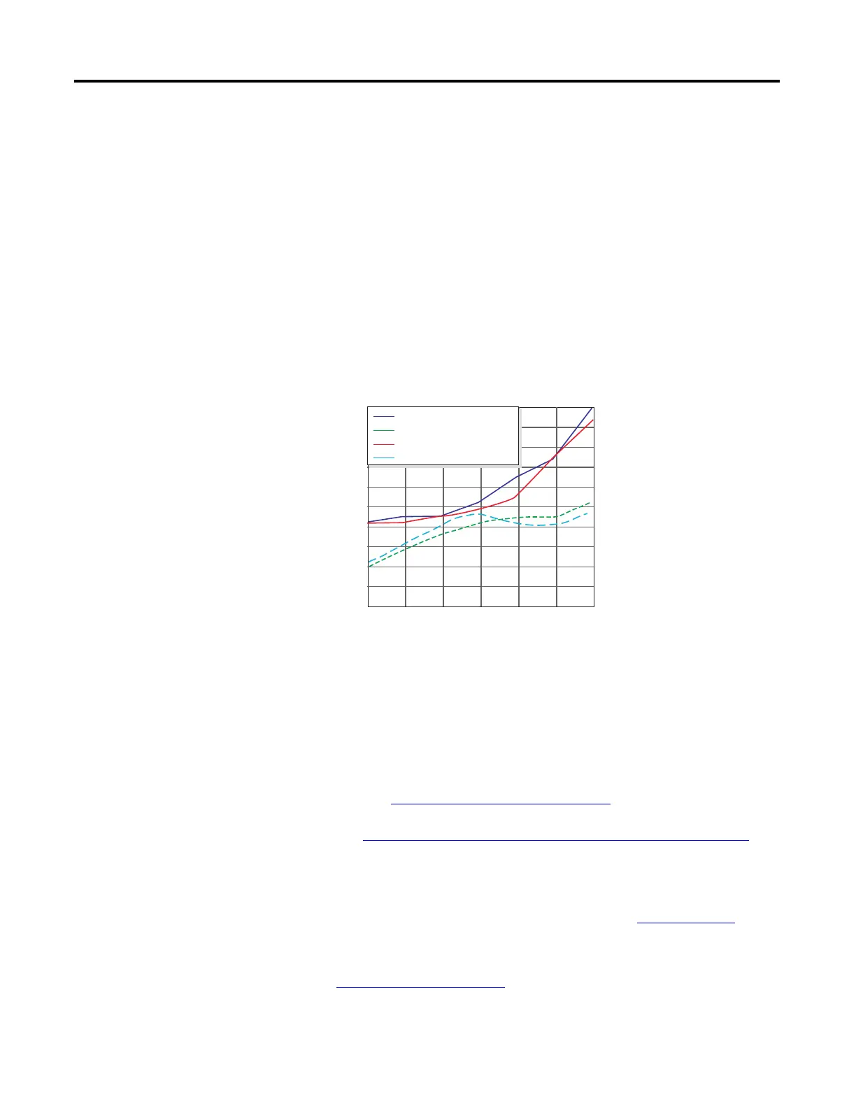
The plot below shows the per unit motor overvoltage as a function of cable
length. This is for no correction versus the modulation correction code for varied
lengths of #12 AWG cable to 600 ft for 4 and 8 kHz carrier frequencies. The
output line-to-line voltage was measured at the motor terminals in 100 ft
increments.
Without the correction, the overvoltage increases to unsafe levels with increasing
cable length for both carrier frequencies. The patented modulation correction
code reduces the overvoltage for both carrier frequencies and maintains a
relatively flat overvoltage level for increasing cable lengths beyond 300 ft.
To determine the maximum recommended motor cable lengths for a particular
drive refer to Cable, Lengths for Motors
on page 26.
Refer to http://www.ab.com/support/abdrives/documentation/index.html
for
detailed technical papers.
RFI Filter Grounding
Refer to the Wiring and Grounding Guidelines for Pulse Width Modulated
(PWM) AC Drives Installation Instructions, publication DRIVES-IN001
, for
detailed information.
S-Curve
See Speed Reference on page 145.
No Correction vs Correction Method at 4 kHz and 8 kHz Carrie
Frequencies - Vbus = 650, fe = 60 Hz
Cable Length (Feet)
per Unit Vout/Vbus
1.6
1.7
1.8
1.9
2
2.1
2.2
2.3
2.4
2.5
2.6
1000 200 400 600300 500
No Correction 4 kHz Carrier
Corrected 4 kHz Carrier
No Correction 8 kHz Carrier
Corrected 8 kHz Carrier
 Loading...


