Rockwell Automation Publication PFLEX-RM003E-EN-E - January 2011 55
Detailed Drive Operation Chapter 1
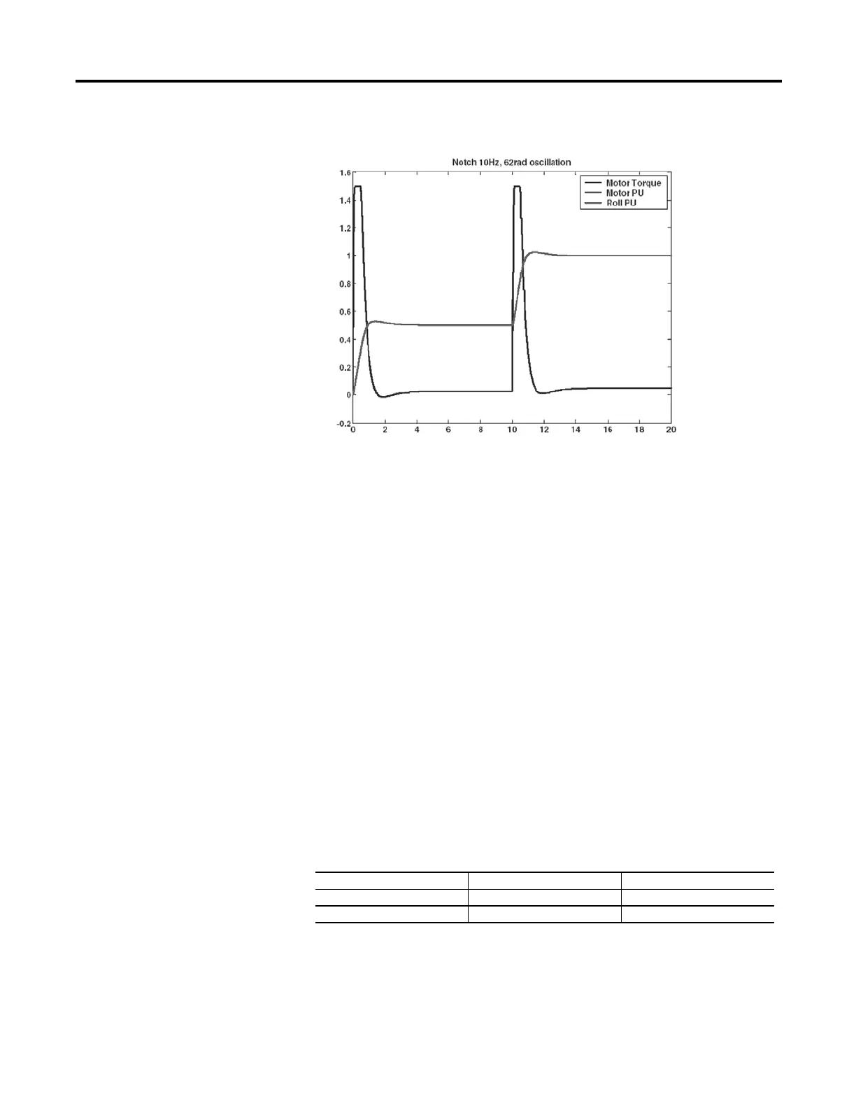
Figure 15 - 10 Hz Notch
Conclusion
There are several filters used in the PowerFlex 700S for various applications.
The process trim uses a simple low pass filter to eliminate undesirable noise in the
feedback circuit. The cut off frequency of the low pass filter is set by parameter
184 [PI Lpass Filt BW]. Typical values would range from 15…20 radians/second.
The speed loop uses a second order low pass filter after the speed error term is
developed. The cut off frequency of the second order low pass filter is set by
parameter 89 [Spd Err Filt BW]. A typical value for this parameter is five times
(5x) the speed loop bandwidth (parameter 90 [Spd Reg BW]).
There are several lead lag filters used in the PowerFlex 700S. The lead lag filter has
two terms. The first term is the filter gain (Kn) and the second term is the filter
frequency (Wn). The filter can be used as “lag” to eliminate noise from entering
the control loop. The filter can be used as a “lead” to increase overall system
performance.
To eliminate noise (lag) use with the light or heavy filter.
Kn Wn
Light 0.7 35
Heavy 0.5 20
 Loading...


