Rockwell Automation Publication PFLEX-RM003E-EN-E - January 2011 17
Detailed Drive Operation Chapter 1
Analog Outputs
Analog Output Specifications
There are two analog outputs, differential, configurable for +/-10V or 0…20 mA.
The D/A (digital to analog) converter is 11 bits plus the sign bit.
Analog Output Configuration
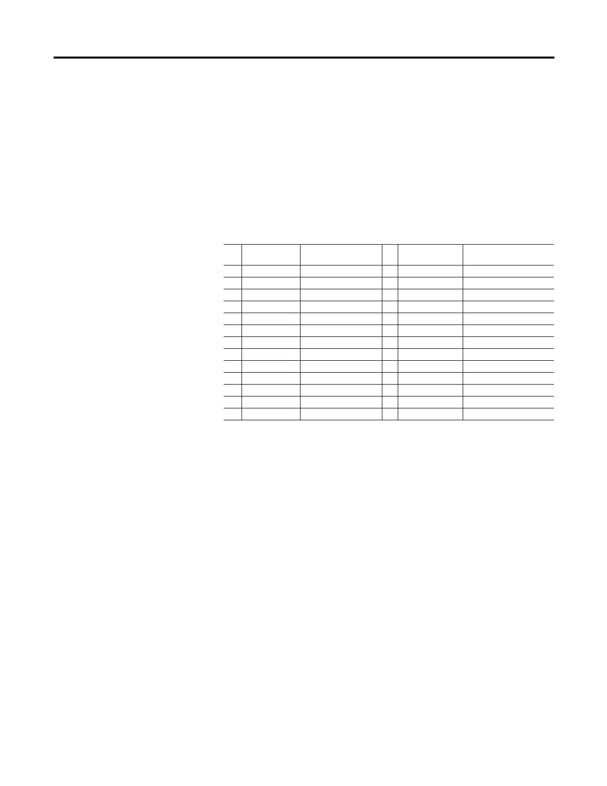
Parameters 831 and 838 [Anlg Outx Sel] are use to specify the signal used on
Analog Outputs 1 and 2, respectively. These parameters can be programmed to
the following selections:
*Additionally, the analog output can be user configured for some other value by
setting [Anlg Outx Sel] to 0 “User Select” and linking either parameter 832 or
839 [Anlg Outx DInt] to a DInt (double integer) parameter or linking parameter
833 or 840 [Anlg Outx Real] to a floating point (real) parameter.
Parameter 834 or 841 [Anlg Outx Offset] is added to [Anlg Outx Real] or [Anlg
Outx DInt] before the scaling and limiting blocks.
The result of [Anlg Outx Offset] plus [Anlg Outx Real] or [Anlg Outx DInt] is
limited by 10 times the value of parameter 835 or 842 [Anlg Outx Scale]. Then
that limited value is divided by the value of [Anlg Outx Scale].
Parameter 836 or 843 [Anlg Outx Zero] is added after the scaling and limiting of
the analog output value. [Anlg Outx Zero] can be used to null out any offset from
the D/A converter.
Parameter 837 or 844 [Anlg Outx Value] displays the voltage or current value for
the analog output.
Bit Selection Corresponding
Parameter
Bit Selection Corresponding
Parameter
0 “User Select” (*see below) 15 “Motor TrqRef” 303 [Motor Torque Ref]
1 “Output Freq” 310 [Output Freq] 16 “MtrTrqCurRef” 305 [Mtr Trq Curr Ref]
2 “Sel Spd Ref” 40 [Selected Spd Ref] 17 “Speed Ref” 301 [Motor Speed Ref]
3 “Output Curr” 308 [Output Current] 18 “Speed Fdbk” 71 [Filtered SpdFdbk]
4 “Trq Cur (Iq)” 499 [Trq Cur Fdbk (Iq)] 19 “Torque Est” 471 [Estimated Torque]
5 “% Motor Flux” 309 [% Motor Flux] 20 “Scl Spd Fdbk” 72 [Scaled Spd Fdbk]
6 “Output Power” 311 [Output Power] 21 “RampedSpdRef” 43 [Ramped Spd Ref]
7 “Output Volts” 307 [Output Voltage] 22 “Spd Reg Out” 101 [SpdReg Integ Out]
8 “DC Bus Volts” 306 [DC Bus Voltage] 23 “MOP Level” 1090 [MOP Level Real]
9 “PI Reference” 181 [PI Reference] 24 “Trend 1 DInt” 572 [Trend Out1 DInt]
10 “PI Feedback” 182 [PI Feedback] 25 “Trend 1 Real” 573 [Trend Out1 Real]
11 “PI Error” 183 [PI Error] 26 “Trend 2 DInt” 576 [Trend Out2 DInt]
12 “PI Output” 180 [PI Output] 27 “Trend 2 Real” 577 [Trend Out2 Real]
 Loading...


