Rockwell Automation Publication PFLEX-RM003E-EN-E - January 2011 63
Detailed Drive Operation Chapter 1
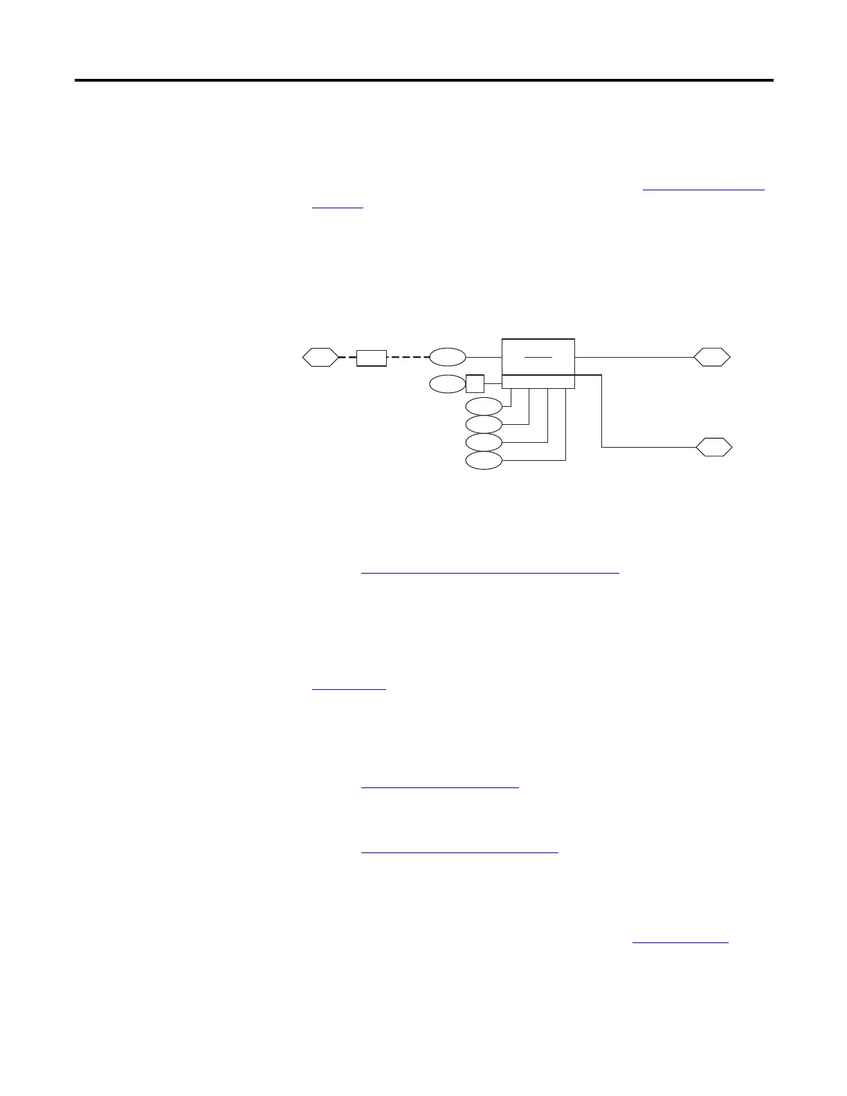
The inertia compensation outputs the calculated torque to the parameter 59
[Inertia Trq Add]. [Inertia Trq Add] is summed with the output of the friction
compensation block and the torque generated by the speed reference loop. That
summed torque enters the torque selection block (refer to Torque Reference
on
page 193 for more information).
Parameter 55 [Speed Comp] contains the rate of acceleration or deceleration
calculated in the inertia compensation block. This parameter is used in following
applications. Link parameter 23 [Speed Trim 3] to [Speed Comp] and set
parameter 24 [SpdTrim 3 Scale] to 0.002 to reduce position error in following
applications.
Input Devices
Contactors
Refer to Motor Start and Stop Precautions on page 74
Circuit Breakers/Fuses
See the PowerFlex 700S AC Drives, Phase II Control Technical Data, publication
20D-TD002
, for Watts Loss data and curves.
Filters EMC
Refer to CE Conformity on page 28
Input Modes
Refer to Start and Stop Modes on page 176.
Input Power Conditioning
Refer to the Wiring and Grounding Guidelines for Pulse Width Modulated
(PWM) AC Drives Installation Instructions, publication DRIVES-IN001
, for
detailed information.
56
9
57
58
43
Inertia Comp
Δn
Δt
Inertia SpeedRef
InertiaAccelGain
InertiaDecelGain
Total Inertia
Logic Command
(Inertia Comp)
59
Link
S Curve Spd Ref
Inertia Torq Add
to Torque
Control [4B1]
60
DeltaSpeedScale
151 10
55
Speed Comp
 Loading...


