42 Rockwell Automation Publication PFLEX-RM003E-EN-E - January 2011
Chapter 1 Detailed Drive Operation
bits. The following chart explains the effect that the direction button on the
HIM has based on the condition of the “Bipolar SRef ” bit:
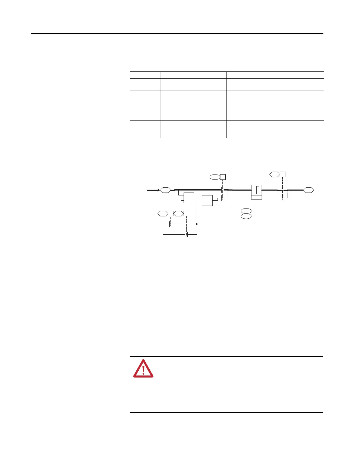
In either Bipolar or Unipolar mode, the selected direction can be determined
from the sign of parameter 41 [Limited Spd Ref ]. Positive values indicate
forward rotation and negative values indicate reverse rotation.
Drive Peripheral Interface
(DPI)
DPI is an enhanced SCANport™ that provides more functions and better
performance. SCANport was a CAN based, Master-Slave protocol, created to
provide a standard way of connecting motor control products and optional
peripheral devices together. It allows multiple (up to 6) devices to communicate
with a motor control product without requiring configuration of the peripheral.
SCANport and DPI both provide two basic message types called Client/Server
(C/S) and Producer/Consumer (P/C). C/S messages are used to transfer
parameter and configuration information in the background (relative to other
message types). P/C messages are used for control and status information. DPI
adds a higher baud rate, brand specific enabling, Peer-to-Peer (P/P)
communication, and Flash Memory programming support. This communication
interface is the primary way to interact with, and control the drive.
Bipolar SRef Reference Controlled by HIM? HIM Direction Button Action
Enabled Yes Changes the motor direction due to a HIM
supplied (+) or (-) command signal.
Enabled No Has no effect on motor direction. Direction
determined by sign of Par 40 [Selected SpdRef].
Disabled Yes Changes the motor direction due to a HIM
supplied forward or reverse [Applied LogicCmd]
bit.
Disabled No Changes the motor direction due to a HIM
supplied forward or reverse [Applied LogicCmd]
bit.
1
0
157 00
0
30
31
0
153 00
Max
X
1
0
Limit
Logic Ctrl State
Control Options
Applied LogicCmd
41
Min Spd Ref Lim
Max Spd Ref Lim
Limited Spd Ref
(Unipol Fwd)
+1
(Unipol Rev ) -1
0
152 21152 20
0
40
Selected Spd Ref
from 3H2
ATTENTION:
• PowerFlex 700S drives only support the DPI communication protocol.
• PowerFlex 700S drives will not communicate with SCANport devices.
• PowerFlex 700S drives do not support LED HIMs.
• PowerFlex 700S drives use a 450 mA device on the 12V DPI power supply.
Due to the typical load of a external DPI device of 140 mA, there is a three
DPI device limit.
 Loading...


