50 Rockwell Automation Publication PFLEX-RM003E-EN-E - January 2011
Chapter 1 Detailed Drive Operation
Figure 8 - Second Order Low Pass Filter
There is a second order low pass filter in the Speed Control-Regulator. This filter
is located after the speed error signal. The break frequency is set by parameter 89
[Spd Err Filt BW]. The break frequency is set to five times (5x) the Speed Loop
Bandwidth. This filter is used to attenuate any high frequency noise that the
speed loop would not be able to control.
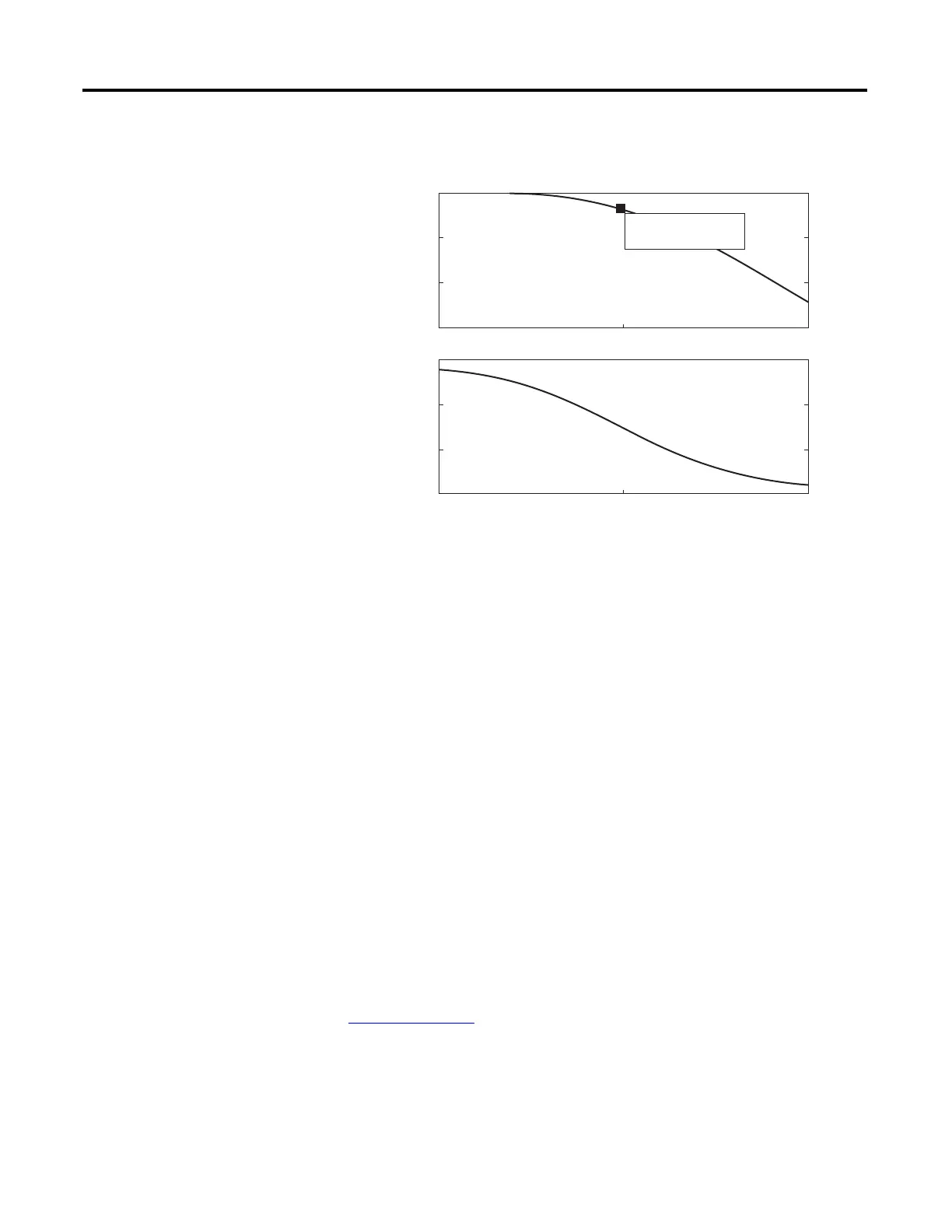
Lead-Lag Filter
The PowerFlex 700S incorporates a generic lead-lag filter. The filter has the
following Laplace transfer function:
Kn is the gain term for the filter and Wn is the frequency term for the filter.
Lead-Lag Filter “lag”
When Kn is less than one (Kn<1) the filter behaves like a low pass filter.
Figure 9 on page 51
shows the lead-lag in a “lag configuration.” The unique aspect
of this filter is that the gain stops once the input frequency is equal to Wn/Kn.
Another aspect to this filter is that there is a mild phase shift during the
attenuation.
Bode Diagram
Magnitude (dB)Phase (deg)
Frequency (rad/sec)
Frequency
0
-10
-20
-30
-40
-50
10
0
10
1
10
2
System: sys
Frequency (rad/sec): 9.85
Magnitude (dB): -5.91
0
-45
-90
-135
-180
Kn s wn+×
swn+
------------------------------
 Loading...


