Rockwell Automation Publication PFLEX-RM003E-EN-E - January 2011 51
Detailed Drive Operation Chapter 1
Figure 9 - Kn < 1 “Lag Filter”
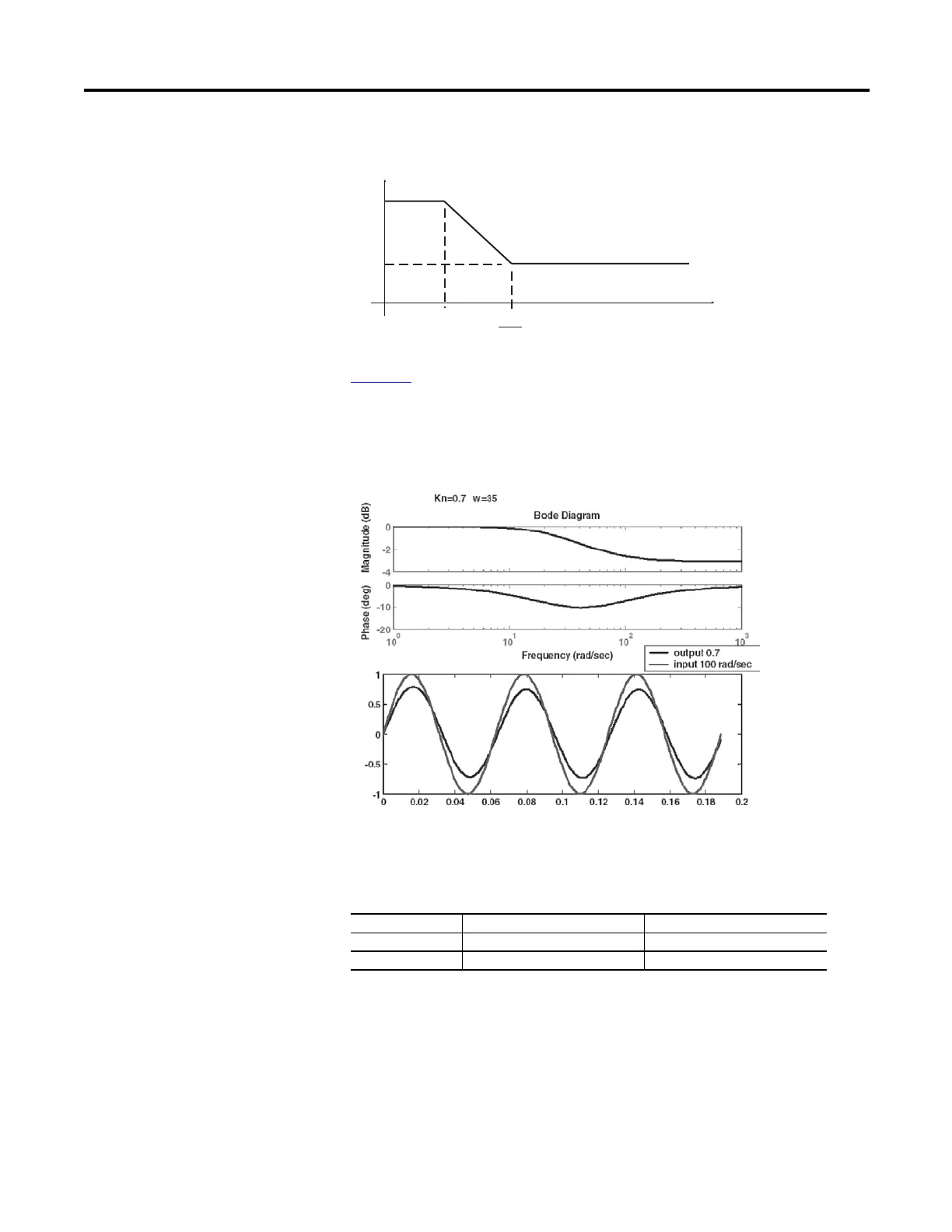
Figure 10 below shows the bode plot of the lag configuration. Kn is set to 0.7 and
Wn is set to 35 radians/second. The time domain shows a 100 radians/second
sinusoidal input. Notice that the phase shift between input and output are
marginal.
Figure 10 - Bode Plot and Time Domain of Lag
The lag configuration is good for eliminating unwanted noise and disturbance
such as backlash. There are two lead-lag blocks used in the speed regulator loop.
One is in the forward path and the other is in the feedback path.
For moderate filtering:
• Set Kn=0.7, Wn=0.35
• For Heavy filtering:
• Set Kn=0.5, Wn=20
Both the Forward and Feedback filters can be set to the same value to increase
their effectiveness.
Kn Wn
Forward Path Parameter 95 [SRegOut FiltGain] Parameter 96 [SReg Out Filt BW]
Feedback Path Parameter 93 [SRegFB Filt Gain] Parameter 94 [SReg FB Filt BW]
gain
1
kn
wn
kn
wn
“Lag” (kn <1)
w (rad/sec)
 Loading...


