198 Rockwell Automation Publication PFLEX-RM003E-EN-E - January 2011
Chapter 1 Detailed Drive Operation
• Set parameter 861 [BitSwap 1A Bit] = 1. This parameter sets the bit that
you would like to turn on in the result, and is set to bit 1 because we want
to use bit swap 1 to turn on bit 1 “Spd S Crv En” of parameter 151 [Logic
Command].
• Link parameter 862 [Bit Swap 1B Data] to parameter 824 [Local I/O
Status]. Parameter 862 [Bit Swap 1B Data] sets the data that you would
like to compare.
• Set parameter 863 [BitSwap 1B Bit] = 3. This parameter indicates that bit
3 of parameter 824 is used. Bit 3 of parameter 824 [Local I/O Status]
indicates that digital input 3 has turned on.
• Link parameter 151 [Logic Command] to parameter 864 [BitSwap 1
Result]. The result of bit swap 1 will control parameter 151.
The overall function of BitSwap 1 is that when digital input 3 turns on, we turn
on bit 1 “Spd S Crv En” of parameter 151 [Logic Command].
For another example using multiple bitswaps and the 16 position selector switch
to control the point to point position with digital inputs see Position Loop -
Point to Point on page 96.
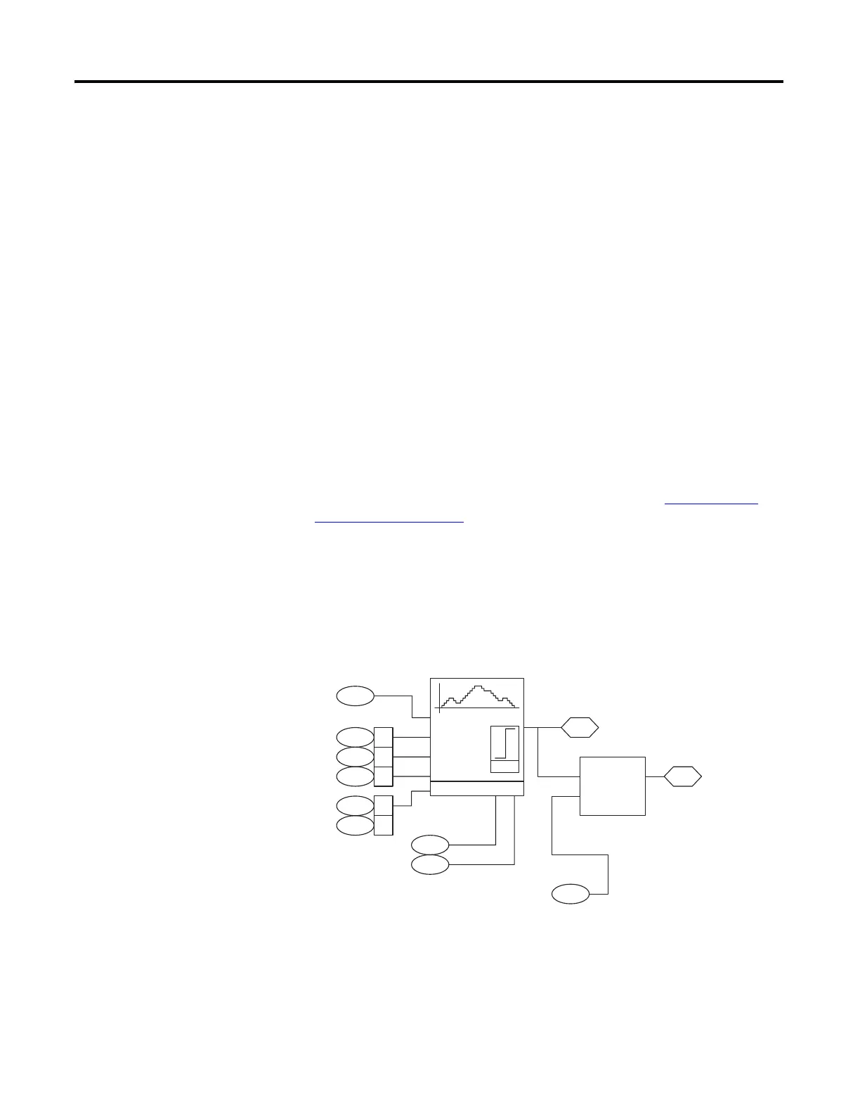
MOP
The motor operated potentiometer (MOP) allows you to increase and decrease a
DInt (double integer) or floating point value using two inputs. The inputs can
come from digital inputs, a network, or DriveLogix.
1087
1086 00
1086 01
1086 02
MOP
Rate
Increment
Decrement
Reset
Limit
1088
1089
1086 03
1086 04
1090
MOP High Limit
MOP Low Limit
1092
Convert
DInt-Real
x Scale
1091MOP Scale DInt
MOP Rate
MOP Control
MOP Level Real
MOP Level DInt
 Loading...


