Rockwell Automation Publication PFLEX-RM003E-EN-E - January 2011 15
Detailed Drive Operation Chapter 1
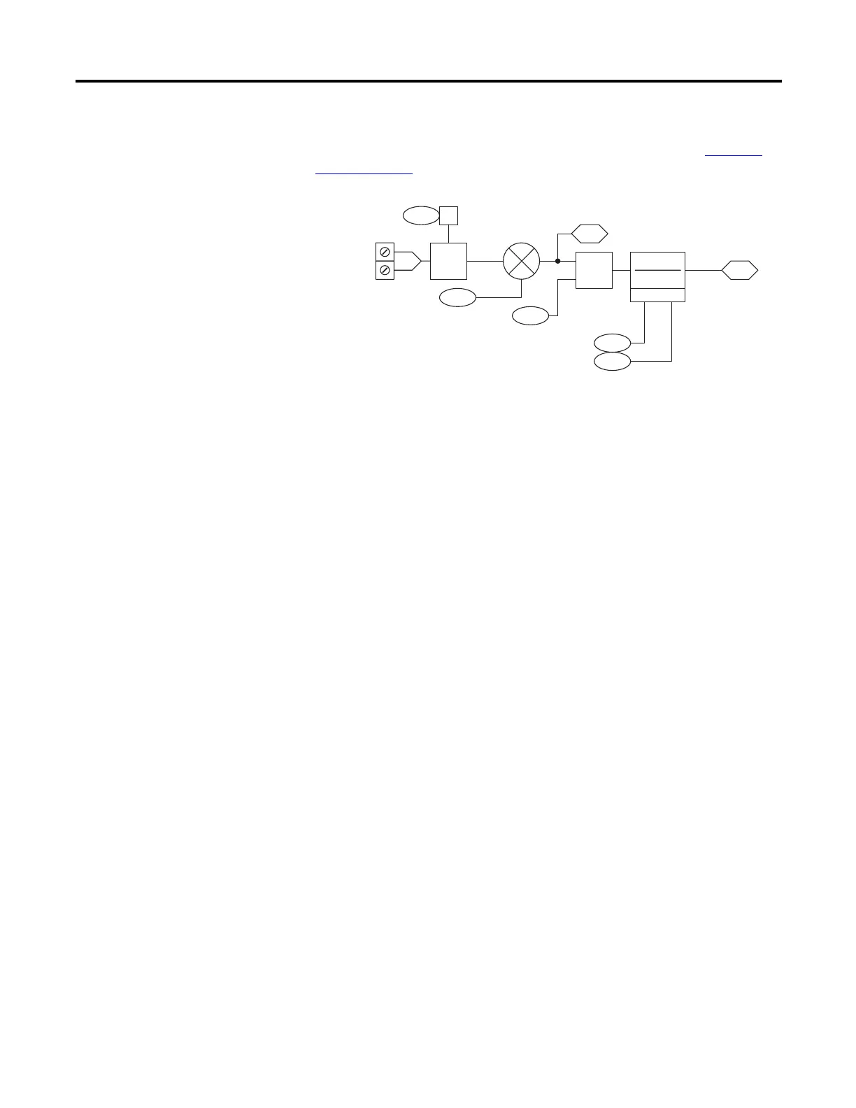
Parameters 804, 810, and 816 [Al x Filt Gain] and parameters 805, 811, and 817
[Anlg Inx Filt BW] are used to filter the analog input data. Refer to Lead-Lag
Filter on page 50 for detailed information.
Configuration Example
This example illustrates how to setup a speed reference to follow a 0…10V analog
input signal and null out a small amount of offset from the A/D converter on the
analog input.
• Parameter 803 [Anlg ln1 Offset] = -0.0144V
• Parameter 802 [Anlg ln1 Scale] = 0.1 per 1V
• Parameter 804 [Al 1 Filt Gain] = 1
• Parameter 805 [Anlg ln1 Filt BW] = 0
• Parameter 10 [Speed Ref 1] is linked to parameter 800 [Anlg ln1 Data]
With a desired parameter 801 [Anlg In1 Value] of 0V, the drive was reading
0.0144V. To null out analog input 1, parameter 803 [Anlg In1 Offset] was set to -
0.0144V.
Parameter 10 [Speed Ref 1] is a per unit parameter, meaning that a value of 1
equates to base motor RPM. Therefore, to scale parameter 800 [Anlg In1 Data]
to give us a value from 0 to 1 for a 0…10V signal, parameter 802 [Anlg In1 Scale]
was set to 0.1 per 1V.
Parameter 805 [Anlg In1 Filt BW] was set to 0 so that no filtering took place on
analog input 1.
A/D
14bit
803
804
805
800
X
802
801
Anlg In1 Offset
Anlg In1 Scale
Anlg In1 Value
Anlg In1 Data
AI 1 Filt Gain
Anlg In1 Filt BW
TB1-01
TB1-02
+
-
Lead Lag
(kn * s)+ wn
s + wn
+
+
821 00
nalog I/O Units
(AI1 Current)
 Loading...


