Rockwell Automation Publication PFLEX-RM003E-EN-E - January 2011 205
Detailed Drive Operation Chapter 1
• Parameter 1024 [Swtch Real 1 NO] is the Normally Open input to the
Real switch. When parameter 1022 [Sel Switch Ctrl], bit 5 is high, this
input is updated to parameter 1025 [Swtch Real 1 Out].
• Parameter 1025 [Swtch Real 1 Out] is the result of the switch. The output
is loaded with the selected input based on parameter 1022 [Sel Switch
Ctrl], bit 5. If this parameter does not update, check the setting of
parameter 1000 [UserFunct Enable] bit 1.
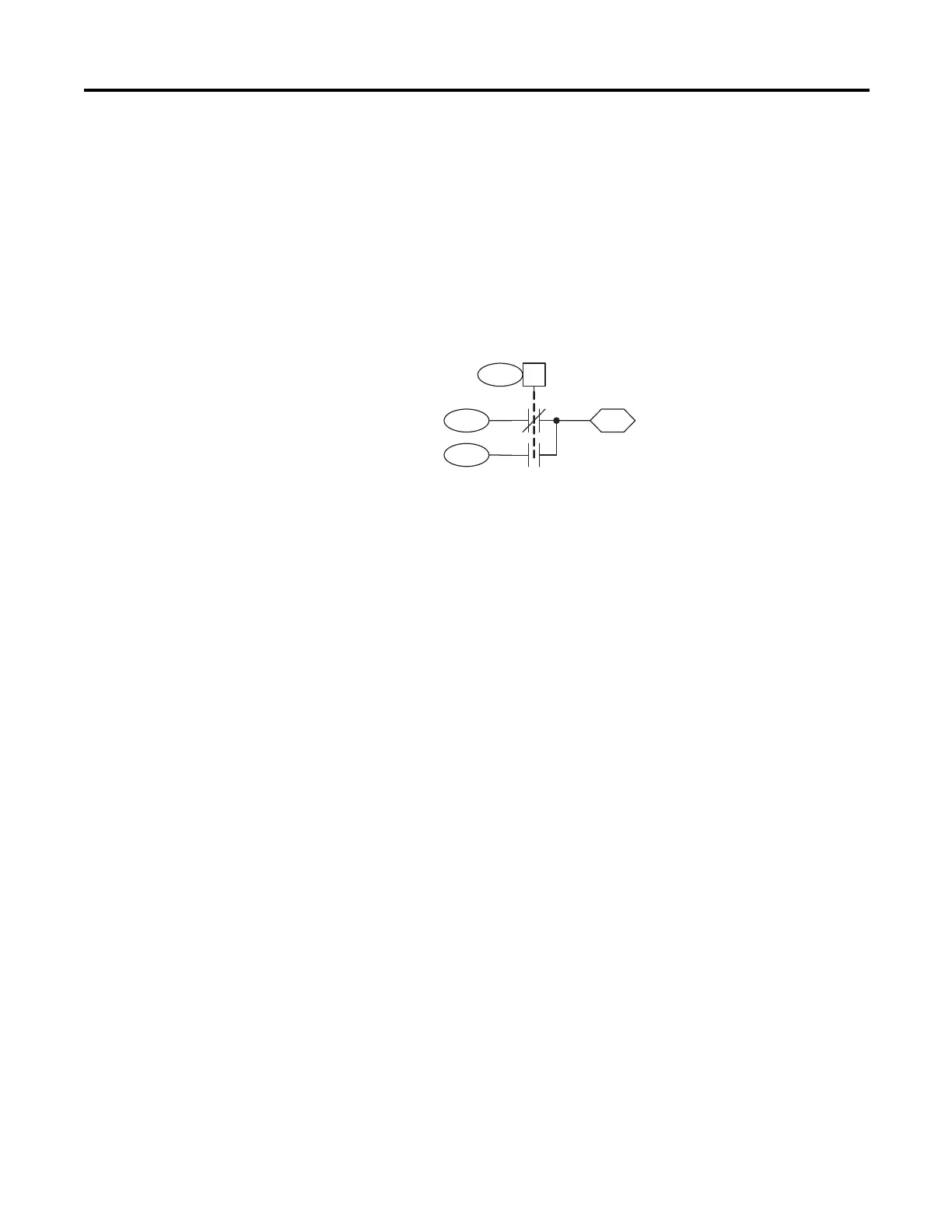
2 Position DInt Switch
Configuration:
• Parameter 1022 [Sel Switch Ctrl], bit 6 “SW DInt 1 On” activates the
switch.
• Parameter 1026 [Swtch DInt 1 NC] is the Normally Closed input to the
DInt switch. When parameter 1022 [Sel Switch Ctrl], bit 6 is low, this
input is updated to Par 1028 [Swtch DInt 1 Out].
• Parameter 1027 [Swtch DInt 1 NO] is the Normally Open input to the
DInt switch. When parameter 1022 [Sel Switch Ctrl], bit 6 is high, this
input is updated to Par 1028 [Swtch DInt 1 Out].
• Parameter 1028 [Swtch DInt 1 Out] is the result of the switch. The output
is loaded with the selected input based on parameter 1022 [Sel Switch
Ctrl], bit 6. If this parameter does not update, check the setting of
parameter 1000 [UserFunct Enable] bit 1.
1027
1026
1022 06
1028
Sel Switch Ctrl
(SW DInt 1 On)
SW DInt 1 Output
0
1
SW DInt 1 NO
SW DInt 1 NC
 Loading...


