EasyManuals Logo

Rockwell Automation Allen-Bradley PowerFlex 755TS Series User Manual

Rockwell Automation Allen-Bradley PowerFlex 755TS Series
196 pages
To Next Page IconTo Next Page
To Previous Page IconTo Previous Page
Page #103 background imageLoading...
Page #103 background image
Rockwell Automation Publication 750-TG101A-EN-P - June 2022 103
Chapter 5 Frame 6 Renewal Kits Installation
8. If installed, disconnect the power wiring from the power terminals.
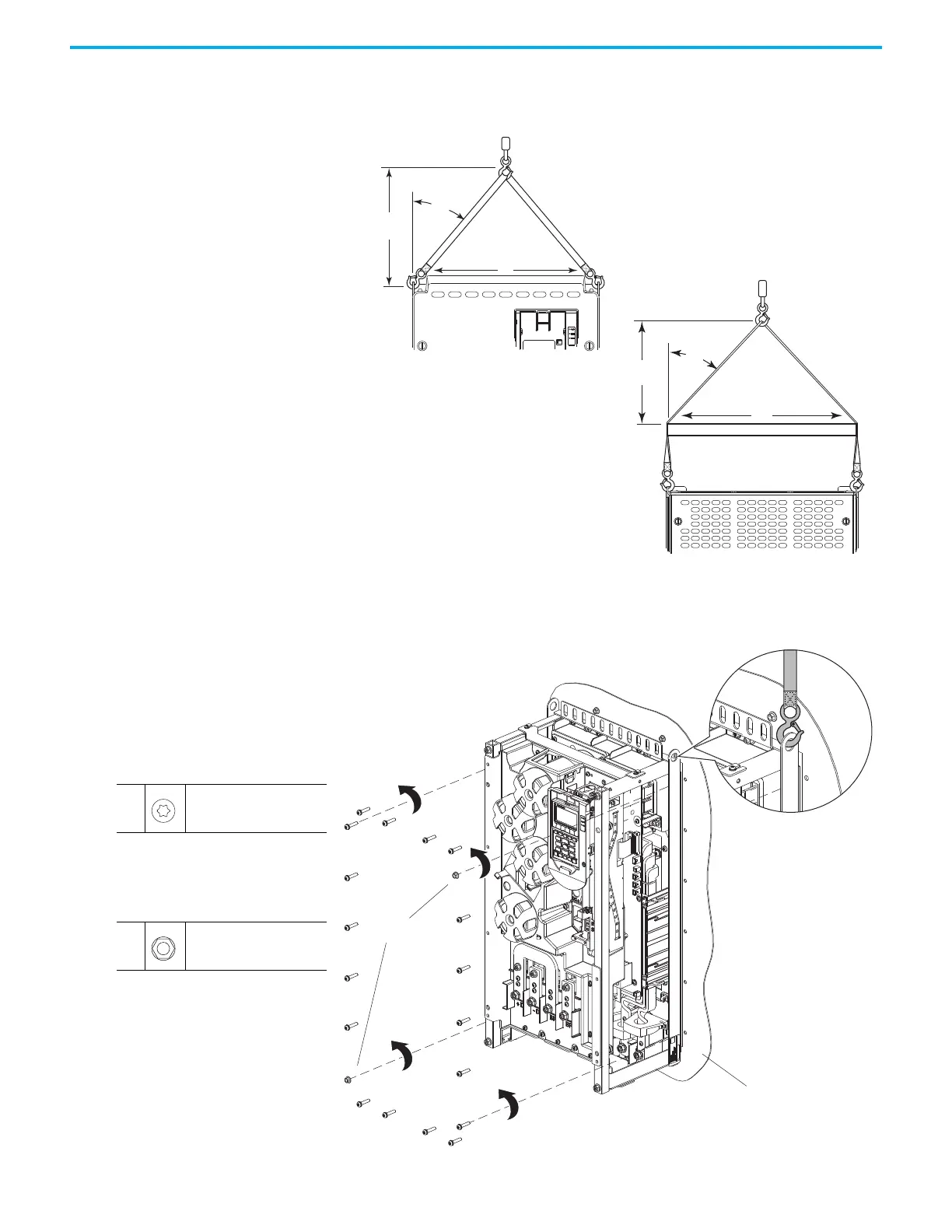
9. Attach the lifting hardware and equipment to the drive according to this
illustration.
10. Remove the two M5 x 0.8 hexagonal nuts that secure the drive chassis to
the flange.
11. Remove the 18 M5 x 25 mm slotted-Torx screws that secure the drive
chassis to the flange.
>
1
/
2 A
A
<45°
>
1
/
2 A
A
<45°
Lifting Hardware Not Shown for Clarity Only.
Panel Mount Surface
10
11
11
M5 x 25 mm
T25
4.5 N
m (40.0 lbin)
10
M5 x 0.8
8 mm
4.5 N
m (40.0 lbin)

Table of Contents

Questions and Answers:

Question and Answer IconNeed help?

Do you have a question about the Rockwell Automation Allen-Bradley PowerFlex 755TS Series and is the answer not in the manual?

Rockwell Automation Allen-Bradley PowerFlex 755TS Series Specifications

General IconGeneral
BrandRockwell Automation
ModelAllen-Bradley PowerFlex 755TS Series
CategoryDC Drives
LanguageEnglish

Related product manuals