Rockwell Automation Publication 750-TG101A-EN-P - June 2022 155
Chapter 6 Frame 7 Renewal Kits Installation
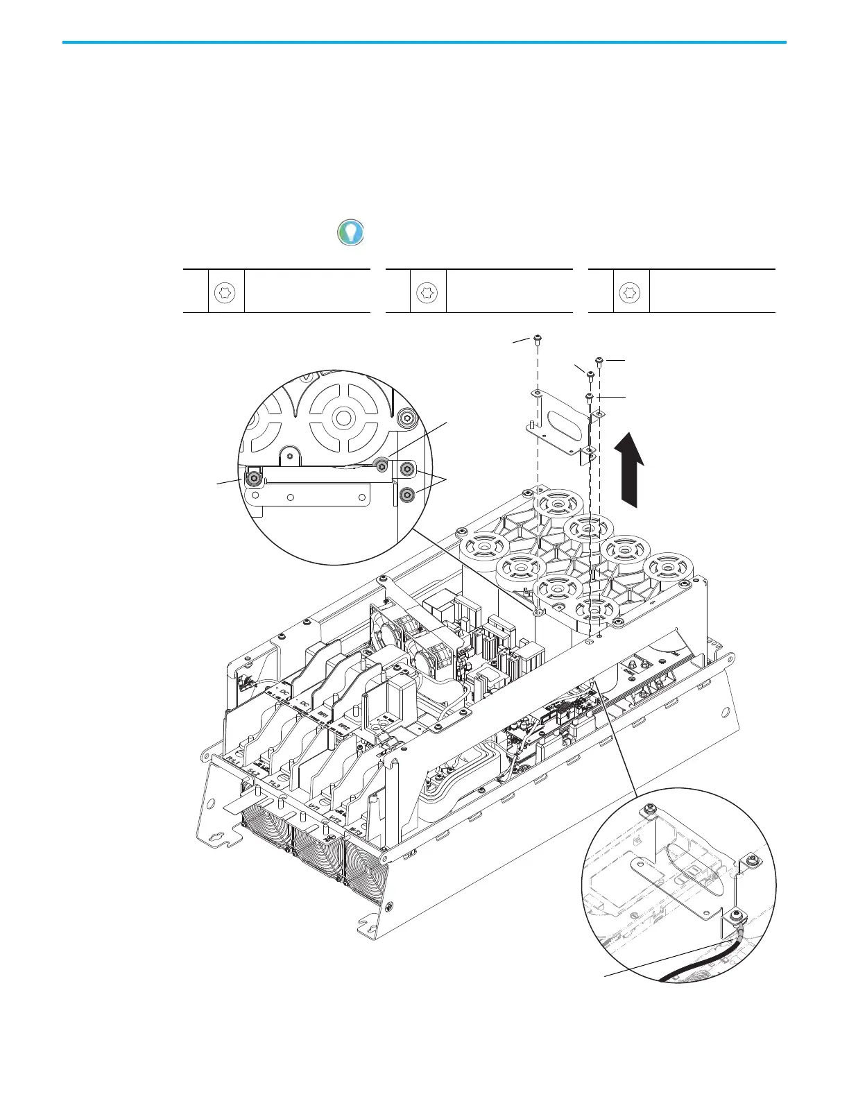
10. Remove the M6 x 16 mm Torx screw that secures the capacitor bank cover
to the control pod support bracket.
11. Complete these steps to remove the control pod support bracket:
a. Remove the M6 x 16 mm Torx screw from the rear, right side of the
control pod support bracket.
b. Remove the two M6 x 16 mm Torx screws from the upper and lower
right side of the control pod support bracket and remove the bracket
from the chassis.
The power interface circuit board ground wire harness is connected to the
screw on the lower right side of the control pod support bracket
10
M6 x 16 mm
T30
6.0 N
•m (53.0 lb•in)
11b
M6 x 16 mm
T30
6.0 N
•m (53.0 lb•in)
11a
M6 x 16 mm
T30
2.6 N
•m (23.0 lb•in)
11a 11b
11a
Power Interface Circuit Board Ground Wire Connection
10
10
11b
11b
 Loading...


