166 Rockwell Automation Publication 750-TG101A-EN-P - June 2022
Chapter 6 Frame 7 Renewal Kits Installation
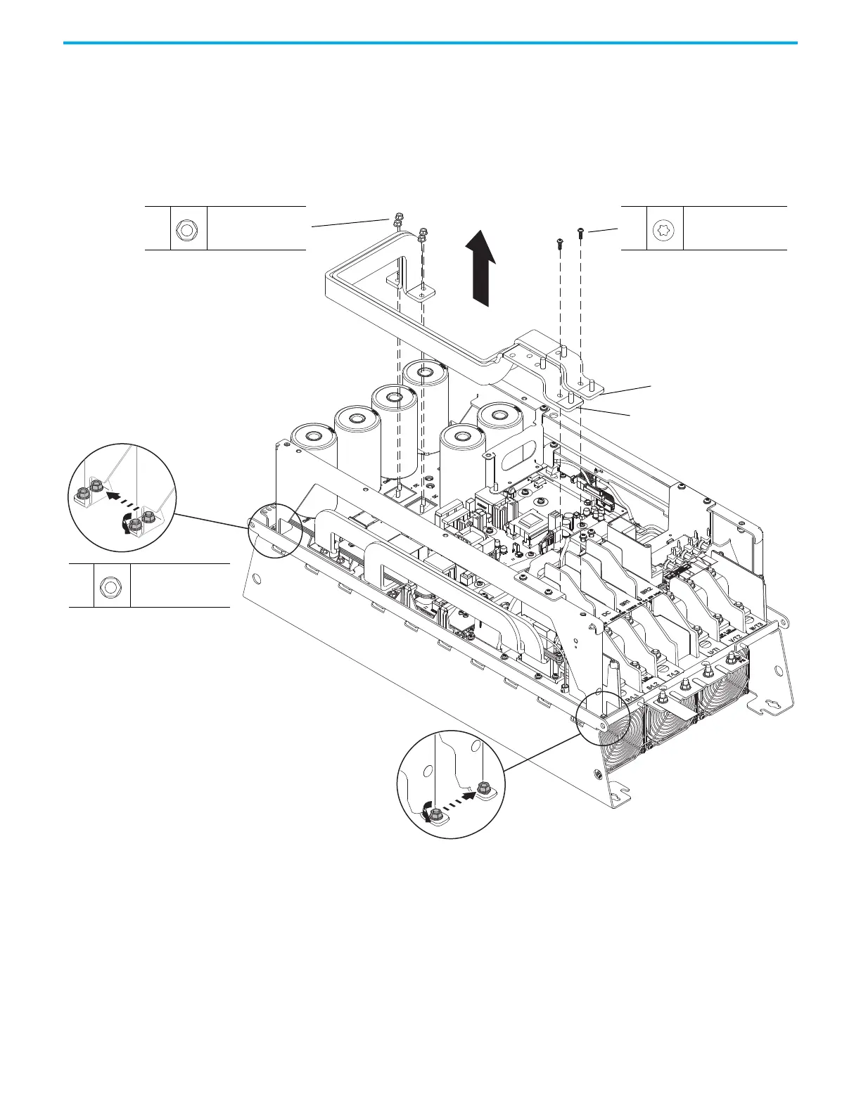
13. If the DC bus bars are installed, complete steps a and b.
a. To allow room to remove the DC bus bars, loosen the three M6 nuts
that secure the left side-rail to the chassis.
b. Remove the four M6 hexagonal nuts that secure the bus bars to the
laminated bus.
c. Remove the two M5 x 16 mm Torx screws that secure the bus bars to
the terminal support and remove the bus bars.
13b
M6
10 mm
5.2 N
•m (46.0 lb•in)
13c
M5 x 16 mm
T25
4.9 N
•m (43.0 lb•in)
+DC Bus Bar
–DC Bus Bar
13a
M6 x 16 mm
T30
5.2 N
•m (46.0 lb•in)
Loosen Only
Loosen Only
13a
13a

 Loading...


