EasyManuals Logo

Rockwell Automation Allen-Bradley PowerFlex 755TS Series User Manual

Rockwell Automation Allen-Bradley PowerFlex 755TS Series
196 pages
To Next Page IconTo Next Page
To Previous Page IconTo Previous Page
Page #167 background imageLoading...
Page #167 background image
Rockwell Automation Publication 750-TG101A-EN-P - June 2022 167
Chapter 6 Frame 7 Renewal Kits Installation
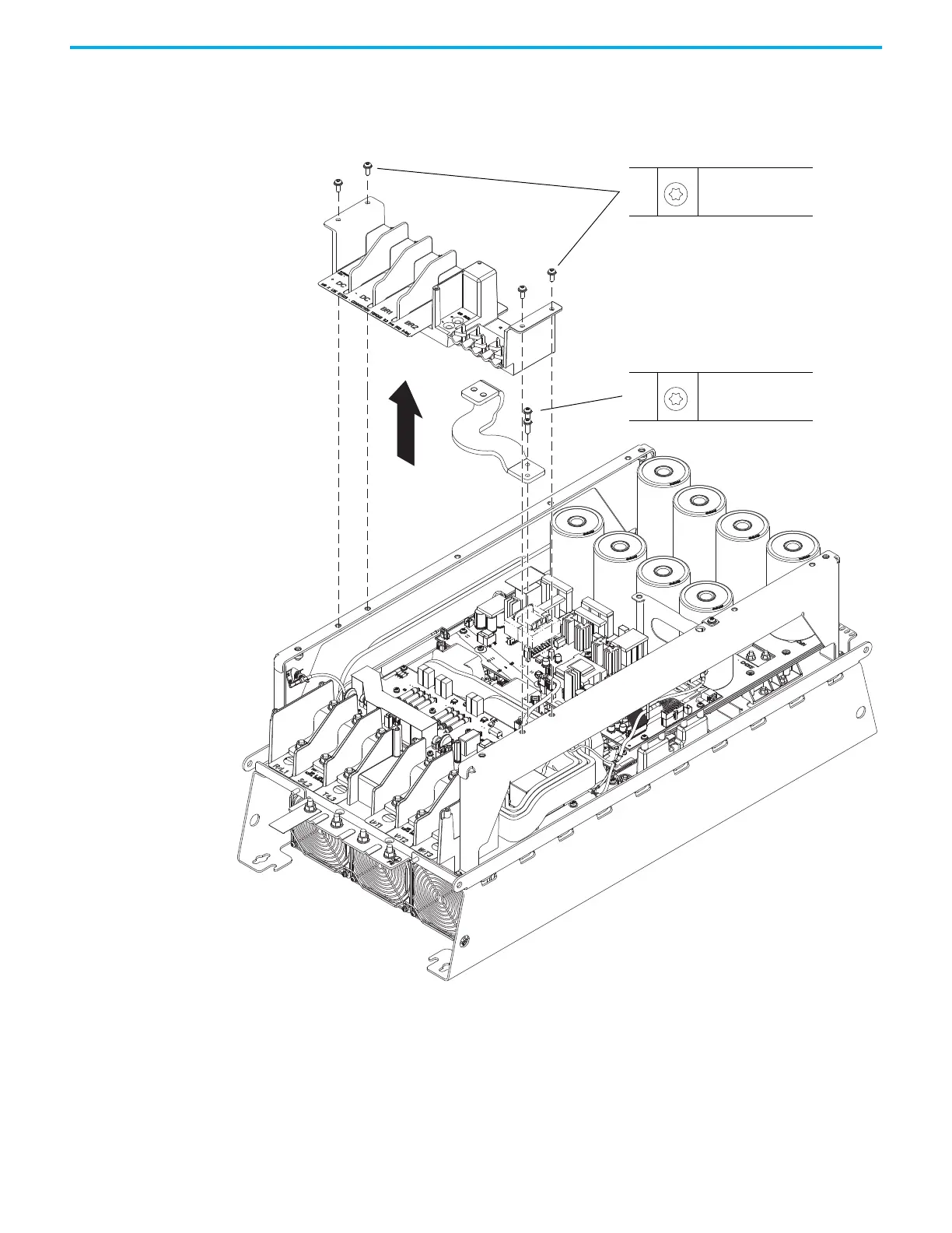
14. Remove the four M6 x 16 mm Torx screws that secure the upper terminal
block support to the chassis and remove the support.
15. Remove the two M6 x 20 mm Torx screws that secure the lower dynamic-
brake bus bar to the brake module and remove the bus bar.
14
M6 x 16 mm
T30
5.2 N
m (46.0 lbin)
15
M6 x 20 mm
T30
5.2 N
m (46.0 lbin)

Table of Contents

Questions and Answers:

Question and Answer IconNeed help?

Do you have a question about the Rockwell Automation Allen-Bradley PowerFlex 755TS Series and is the answer not in the manual?

Rockwell Automation Allen-Bradley PowerFlex 755TS Series Specifications

General IconGeneral
BrandRockwell Automation
ModelAllen-Bradley PowerFlex 755TS Series
CategoryDC Drives
LanguageEnglish

Related product manuals