Rockwell Automation Publication 750-TG101A-EN-P - June 2022 171
Chapter 6 Frame 7 Renewal Kits Installation
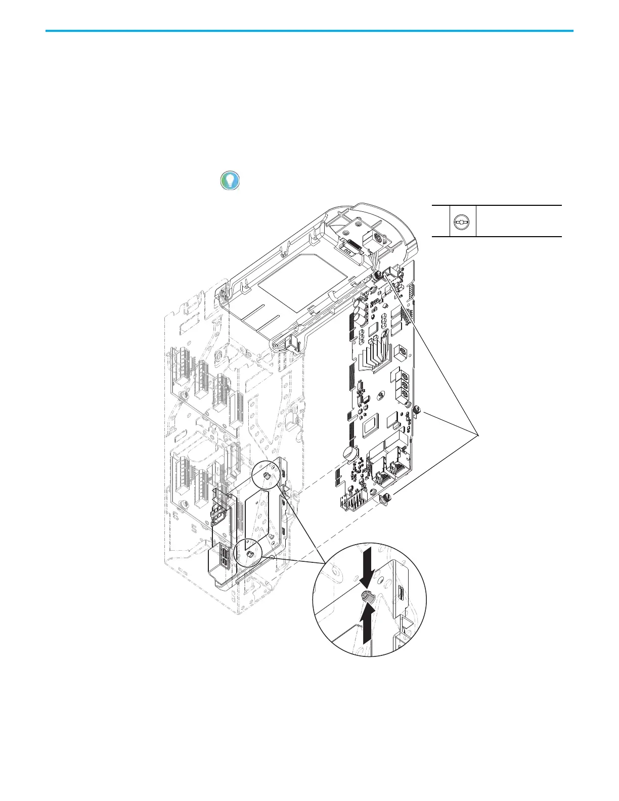
5. If a torque accuracy module (TAM) is installed, complete steps a and c.
a. Loosen the screw that secures the HIM cradle to the pod chassis, and
rotate the cradle up to a 90° horizontal position (see previous image).
b. Loosen the three M3 captive slotted-Torx screws that secure the main
control circuit board to the control pod chassis and remove the main
control board.
c. On the interior of the control pod chassis, compress the two posts that
secure the TAM to the control pod and push the posts through the
mounting holes.
The TAM remains in the drive chassis and connected to the power interface circuit
board via a wire harness after the control pod chassis is removed.
5a,
5b
M3 x 6.4 mm
T15 or F - 5 mm (0.19 in.)
0.45 N•m (4.0 lb•in)
5b
5c (Qty. 2)

 Loading...


