EasyManuals Logo

Rockwell Automation Allen-Bradley PowerFlex 755TS Series User Manual

Rockwell Automation Allen-Bradley PowerFlex 755TS Series
196 pages
To Next Page IconTo Next Page
To Previous Page IconTo Previous Page
Page #172 background imageLoading...
Page #172 background image
172 Rockwell Automation Publication 750-TG101A-EN-P - June 2022
Chapter 6 Frame 7 Renewal Kits Installation
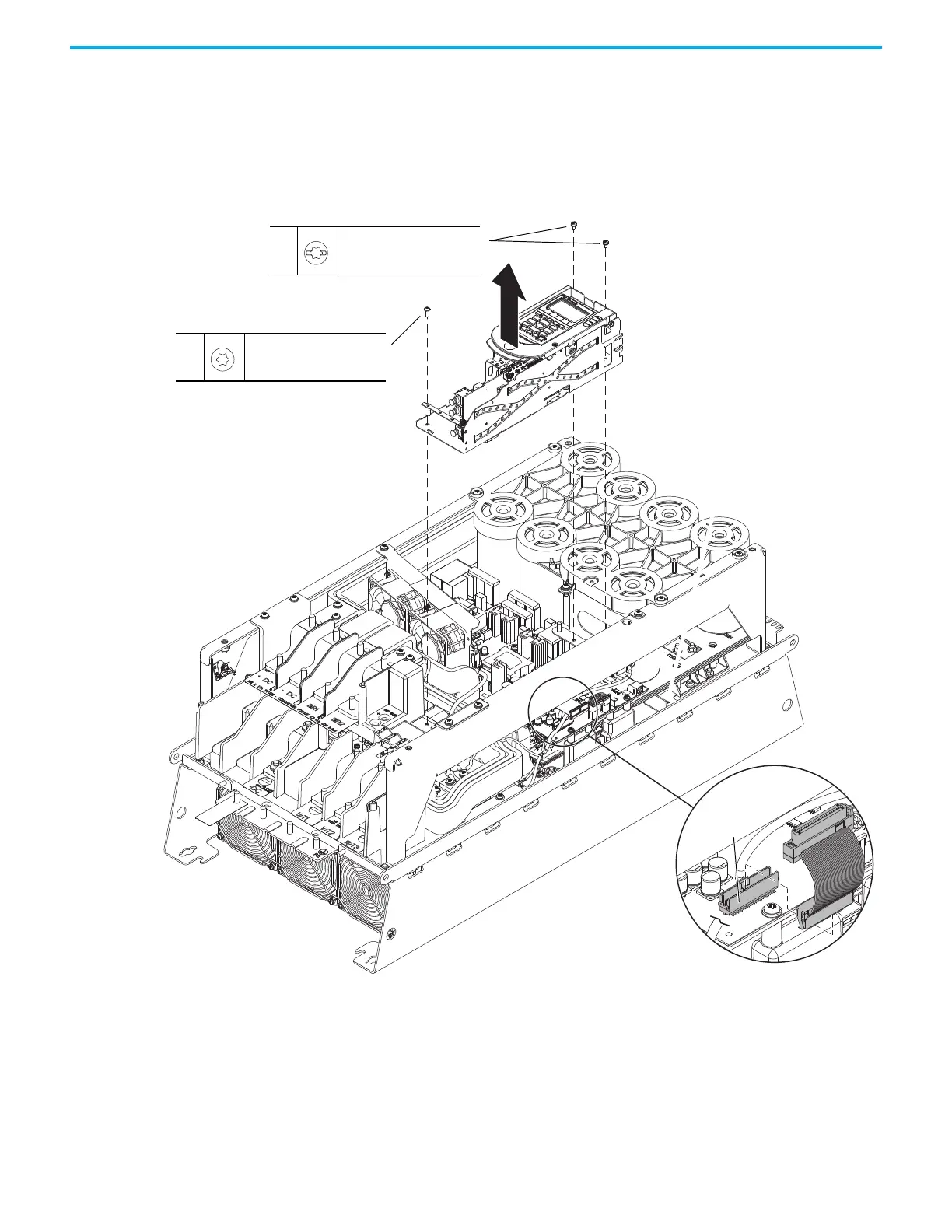
6. Disconnect the ribbon cable from connector J1 on the power interface
circuit board below the control pod.
7. Remove the two M4 x 8 mm slotted-Torx screws that secure the upper
control pod chassis to the drive chassis.
8. Remove the M6 x 12 mm Torx screw that secures the lower control pod
chassis to the drive chassis.
9. Remove the control pod carefully from the drive.
7
M4 x 8 mm
T20
2.3 N
m (20.0 lbin)
8
M6 x 12 mm
T30
2.6 N
m (23.0 lbin)
9
6
Ribbon Cable Shown Removed from the Back of
the Control Pod Chassis for Clarity Only.
J1

Table of Contents

Questions and Answers:

Question and Answer IconNeed help?

Do you have a question about the Rockwell Automation Allen-Bradley PowerFlex 755TS Series and is the answer not in the manual?

Rockwell Automation Allen-Bradley PowerFlex 755TS Series Specifications

General IconGeneral
BrandRockwell Automation
ModelAllen-Bradley PowerFlex 755TS Series
CategoryDC Drives
LanguageEnglish

Related product manuals