Rockwell Automation Publication 750-TG101A-EN-P - June 2022 73
Chapter 4 Frames 1…5 Renewal Kits Installation
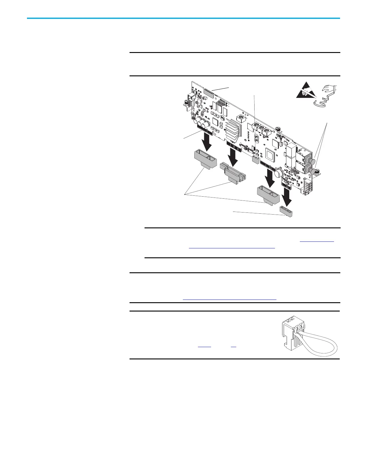
1. For kit catalog number SK-RT-MCB1-PF755-XT only, hold the tab on the
protective cover and carefully remove the cover from the edge connector
on the circuit board. Do not touch the edge connector.
2. Install the main control circuit board in the reverse order of removal.
3. Make any necessary changes to the settings on these main control board
selectors or jumpers:
• Control switch
• Embedded EtherNet/IP address switches
• Hardware enable jumper
• Safety enable jumper
IMPORTANT If a Torque Accuracy Module (TAM) is not installed, do not remove the
protective cover from the edge connector that is identified in the
illustration.
IMPORTANT If before installation, grease is removed from an edge connector or
is contaminated, do not install the circuit board. See Apply Dielectric
Grease to an Edge Connector on page 18 for instructions on how to
clean and grease an edge connector.
IMPORTANT Do not remove protective covers unless used at the time of installation. For
the product to meet the corrosive atmosphere rating, protective covers
must remain installed in unused connectors during storage and operation.
See Protective Covers on Kits with XT
on page 16 for details.
IMPORTANT
For frames 4 and 5, IP54, NEMA/UL Type 12
drives only, be sure to install jumper J16 into
connector P16 on the main control circuit
board. See step 8
on page 65 for details.
Hold Protective Cover by Tab.
Remove Only when Used
Dielectric Grease on Connectors
(Grease is Translucent - Shown
Shaded for Example Only)
Main Control Circuit Board Shown
Remove Only when a Torque
Accuracy Module is Installed.
Do Not Remove these Protective Covers
(for Factory User Only).
Remove Only when EtherNet/IP™
Cables are Installed.

 Loading...


