Mounting the Drive 3-3
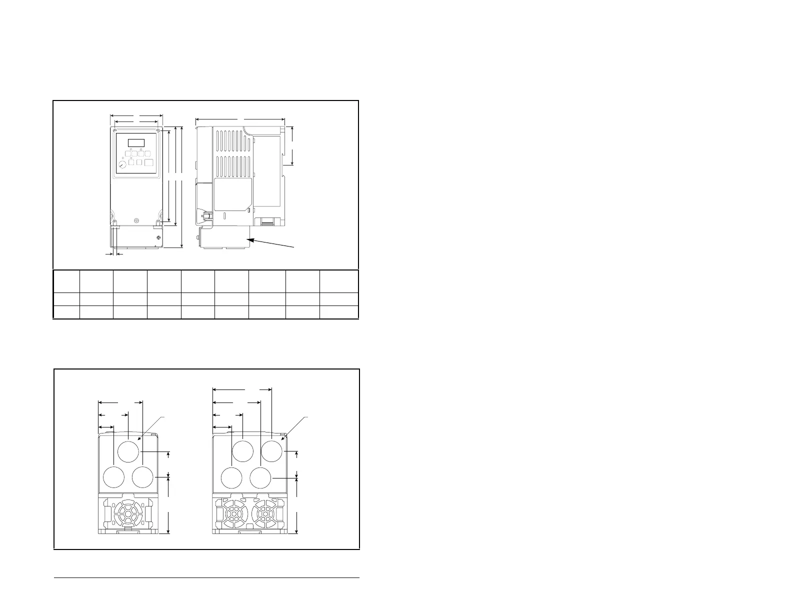
3.1.3 Mounting Dimensions for the MD60 Drive
Overall dimensions and weights are illustrated in figures 3.2 and 3.3
as an aid to calculating the total area required by the MD60 drive.
Dimensions are in millimeters and (inches). Weights are in
kilograms and (pounds). See table 2.1 for drive ratings by frame.
Frame A B
1
CDE
2
FG
Shipping
Weight
A 80 (3.15) 185 (7.28) 136 (5.35) 67 (2.64) 152 (5.98) 59.3 (2.33) 140 (5.51) 1.4 (3.1)
B 100 (3.94) 213 (8.39) 136 (5.35) 87 (3.43) 180 (7.09) 87.4 (3.44) 168 (6.61) 2.2 (4.9)
Figure 3.2 – Drive Dimensions - Front View
1
Height dimension includes NEMA 1/IP30 Kit; see figure 3.3.
2
Height dimension without NEMA 1/IP30 Kit.
A
GE
D
C
B
5.5 (0.22)
Front
Side
NEMA 1/IP30
Kit
Figure 3.3 – Drive Dimensions - Bottom View
59.2
(2.33)
40.0
(1.57)
20.7
(0.81)
75.3
(2.96)
34.0
(1.34)
74.3
(2.93)
35.6
(1.40)
64.1
(2.52)
79.1
(3.11)
40.6
(1.60)
25.6
(1.01)
∅ 22.2
(0.88)
∅ 22.2
(0.88)
Frame A Frame B
 Loading...