Wiring 3-25
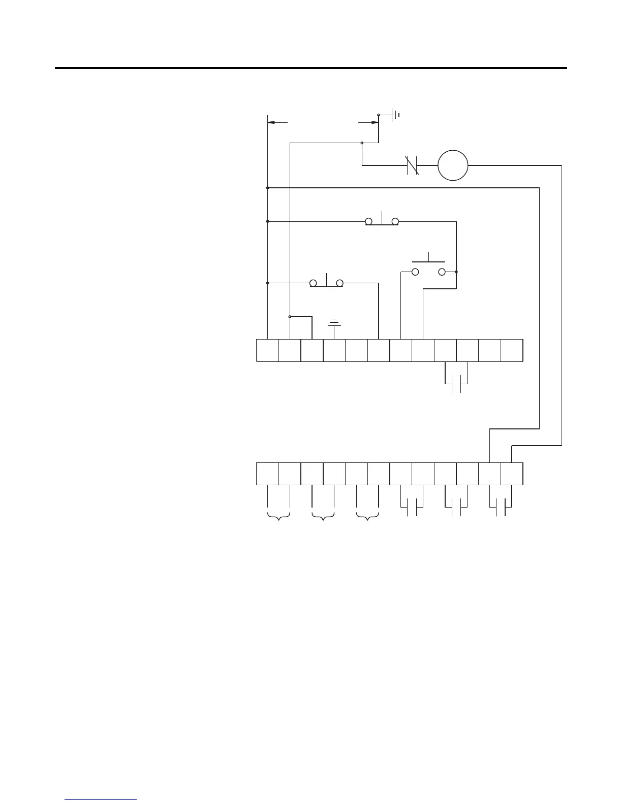
Figure 3.23 Typical Retrofit Wiring Diagram
➀
Customer supplied.
➁ Overload protection should be disabled in the SMC-Flex controller.
➂ Refer to the controller nameplate to verify the rating of the control power input voltage.
For units rated 625…1250 A, terminals 11 & 12 are factory pre-wired from terminal block
CP1 - terminals 1 & 4.
➃ Soft Stop, Pump Stop, or Brake.
➄ Aux #4 should be set to normal operation.
Note: Refer to Chapter 3 for typical power circuits.
11 12
13
14
15 16
17
18 19 20
21
23
24
25 26
27
28 29
30 31 32 33
22
34
Option Stop
Start
M
OL
Aux #3Aux #2
Aux #4
Aux #1
SMC-Flex
Control Terminals
Control Power
Stop
PTC
Input
TACH
Input
Ground
Fault
➀
➄
➀
➀
➂
➀➃
➀➁

 Loading...


