2-3
Level Controller Overview and Installation
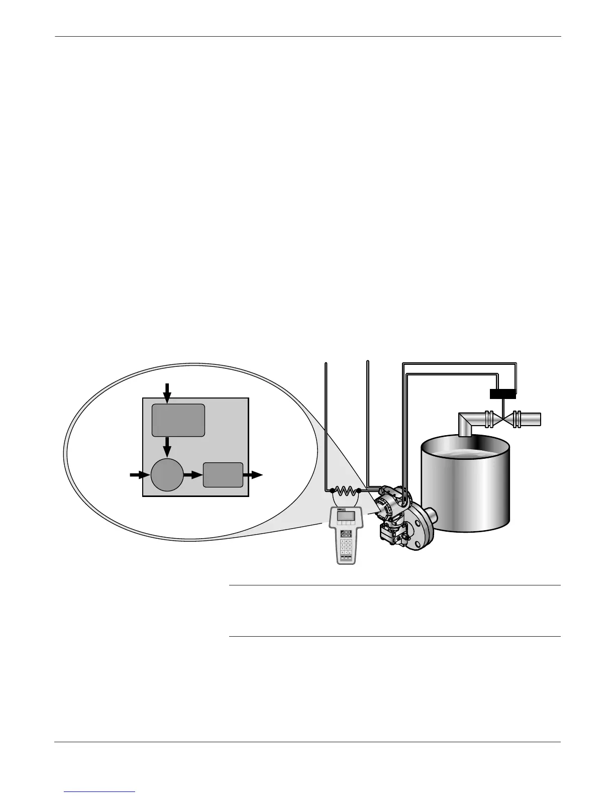
Figure 2-1 illustrates a single loop level control system. The single
control loop consists of:
• A level process.
• A Level Controller with a 4–20 mA control output signal.
• An electrical-to-pneumatic converting device such as a 3311 I/P.
• An optional positioner device to correct for valve displacement
before valve variations affect the process.
• An actuator device such as a valve.
Figure 2-2 is a more detailed diagram of the level process depicted in
Figure 2-1. The setpoint is the desired process value at which the user
wishes to maintain (control) the process. The error between the setpoint
and the actual process variable (as measured by the sensor) is used by
the controller to determine the value of its output.
The controller output is an electrical current (in mA) which is used by
an electrical-to-pneumatic device, such as an I/P, to control the position
of a valve. A positioner, which is mechanically connected to the moving
part of the valve, automatically adjusts its output pressure in order to
maintain a desired position that bears a predetermined relationship to
the input signal.
FIGURE 2-2. Level Controller
Process Diagram
NOTE
The Level Controller differs from a standard transmitter in
that the 4–20 mA output is a control output, not a differential
pressure (DP) output.
3095\3095_10A
SETPOINT
Level Target
Tank
Level
PID
4–20 mA
Valve
Position