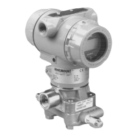
Rosemount Model 3095 Multivariable
™
Level Controller
2-8
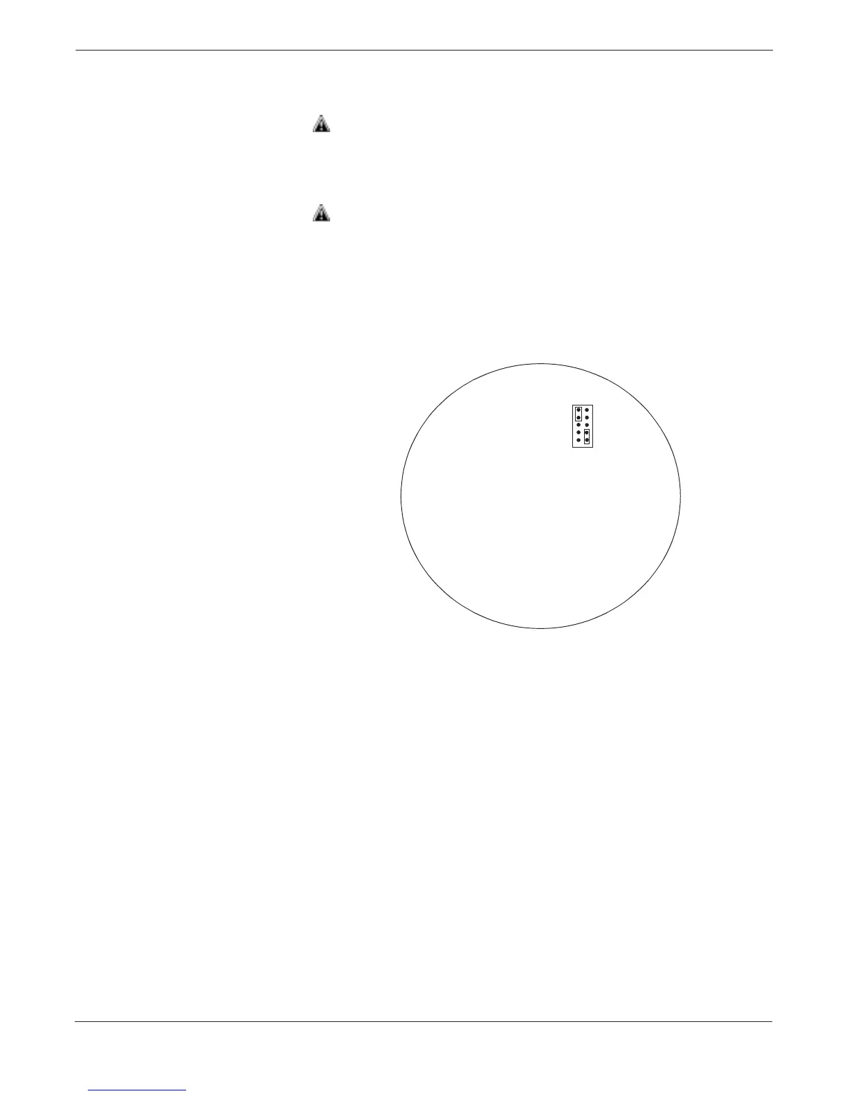
Use the following steps to change the jumper settings:
1. If the controller is installed, secure the loop and remove power.
2. Remove the housing cover opposite the field terminal side. Do not
remove the instrument cover in explosive atmospheres when the
circuit is alive.
3. Locate the jumper(s) on the output electronics board (see Figure
2-5), then move the jumper(s) to the desired setting.
4. Reattach the housing cover. Metal to metal contact is preferred.
Both controller covers must be fully engaged to meet explosion-
proof requirements.
5. If the controller is installed, reapply power.
OUTPUT ELECTRONICS BOARD
OFF
ON
ALARM
<
<
SECURITY
>
>
HI
LO
NOTE
Security jumper not installed = Not Write Protected.
Alarm jumper not installed = High Alarm.
FIGURE 2-5. Write Protect and
Level Controller Alarm Jumpers.
3095-3095G05A, 3095H05A