Rosemount Model 3095 Multivariable
™
Level Controller
5-4
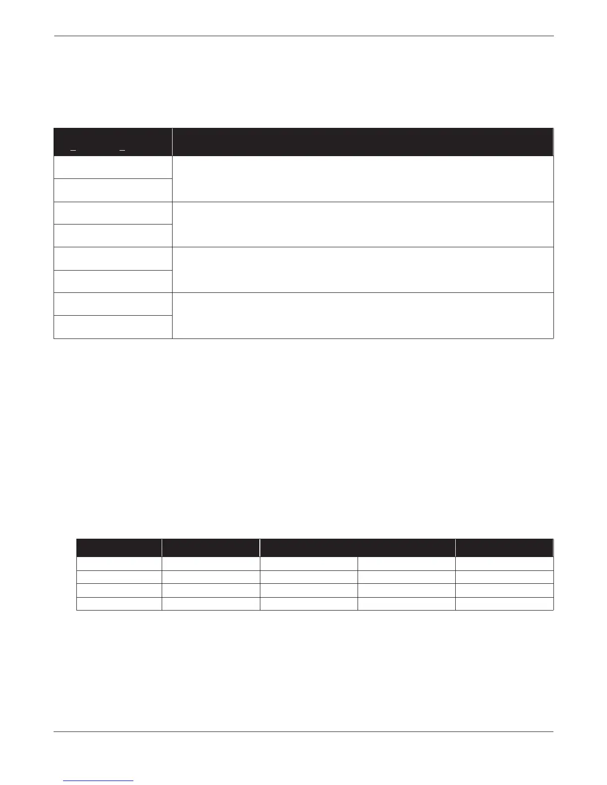
Overrange Conditions Overrange conditions are typically caused by an error in which the
sensor or level measurements have reached an overrange condition
where substitute values are being used.
TABLE 5-3. Corrective Action:
Overrange Conditions.
Sensor Limits and Alarm
Abbreviation
Table 5-4 identifies sensor limits. Standard alarm abbreviations used
in alarm Tables 5-3 and 5-4 are:
LRL Lower Range Limits
URL Upper Range Limits
LRV Lower Range Value
URV Upper Range Value
URL+ URL + (10%URL)
(For example, URL+ = 250 + (0.10 3 250) = 275
LRL– LRL – (10%LRL)
(For example, LRL– = –250 –[0.10 3 (250)] = –275
TABLE 5-4. Level Controller
Sensor Limits.
(1) LRL– is equal to LRV and lower sensor trim limits.
(2) URL+ is equal to URV and upper sensor trim limits.
(3) In the fixed temperature mode, PT range is –459 to 3500 °F (–273 to 1927 °C).
(4) For Alpha Two field trial units, PT URL is 800 °F (427 °C).
Alarm text as displayed in
D
iagnostics, Error Info
Corrective Action
DP above URL+
These displays indicate that the device differential pressure reading exceeds its sensor limits by more than 10%.
There are two possible causes; either the device is overpressured (underpressured), or it has a sensor
malfunction. Check the pressure input to the device. If an overpressure (underpressure) condition exists, correct it.
If not, replace the sensor module as described on page 5-11.
DP below LRL–
Working Pressure above URL+
These displays indicate that the device absolute pressure reading exceeds its sensor limits by more than 10%.
There are two possible causes; either the device is overpressured (underpressured), or it has a sensor
malfunction. Check the pressure input to the device. If an overpressure (underpressure) condition exists, correct it.
If not, replace the sensor module as described on page 5-11.
Working Pressure below LRL–
PT above URL+
Check the device RTD connector and RTD screw terminals to ensure that the RTD cable is properly connected.
Verify that the process temperature is between –40 °F and 1200 °F.
PT below LRL–
ST above URL+
These displays indicate that the ambient temperature limit of the device is being exceeded. Verify that the device
ambient temperature is between –40 °F and 185 °F. If device temperature exceeds these limits, correct the
temperature. If device temperature is within these limits, replace the sensor module as described on page 5-11.
ST below LRL–
Sensor LRL–
(1)
LRL URL URL+
(2)
DP Range 2 –275 inH
2
0 at 68 °F –250 inH
2
0 at 68 °F 250 inH
2
0 at 68 °F 275 inH
2
0 at 68 °F
DP Range 3 –913 inH
2
0 at 68 °F –830 inH
2
0 at 68 °F 830 inH
2
0 at 68 °F 913 inH
2
0 at 68 °F
PT
(3)
–44 °F (–42 °C) –40 °F (–40 °C) 1200 °F (649 °C)
(4)
1220 °F (660 °C)
Sensor Temperature –44 °C –40 °C 85 °C 93.5 °C