Reference Manual
00809-0100-4021, Rev FB
August 2011
A-7
Rosemount 3144P
Local Display
Optional five-digit LCD display includes 0–100% bar graph. Digits are
0.4 inches (8 mm) high. Display options include engineering units (°F, °C, °R,
K, ohms, and millivolts), percent, and milliamperes. The display can also be
set to alternate between engineering units/milliamperes, Sensor 1/Sensor 2,
Sensor 1/Sensor 2/Differential Temperature, and Sensor 1/Sensor2/Average
Temperature. All display options, including the decimal point, may be
reconfigured in the field using a Field Communicator or AMS.
Turn-on Time
Specification performance is achieved less than 6 seconds after power is
applied to the transmitter when the damping value is set to 0 seconds.
Power Supply Effect
Less than ±0.005% of span per volt.
SIS Safety Transmitter Failure Values
IEC 61508 Safety Certified SIL 2 Claim Limit
• Safety accuracy: 2.0%
(1)
or 2 °C (3.6 °F), whichever is greater
• Safety response time: 5 seconds
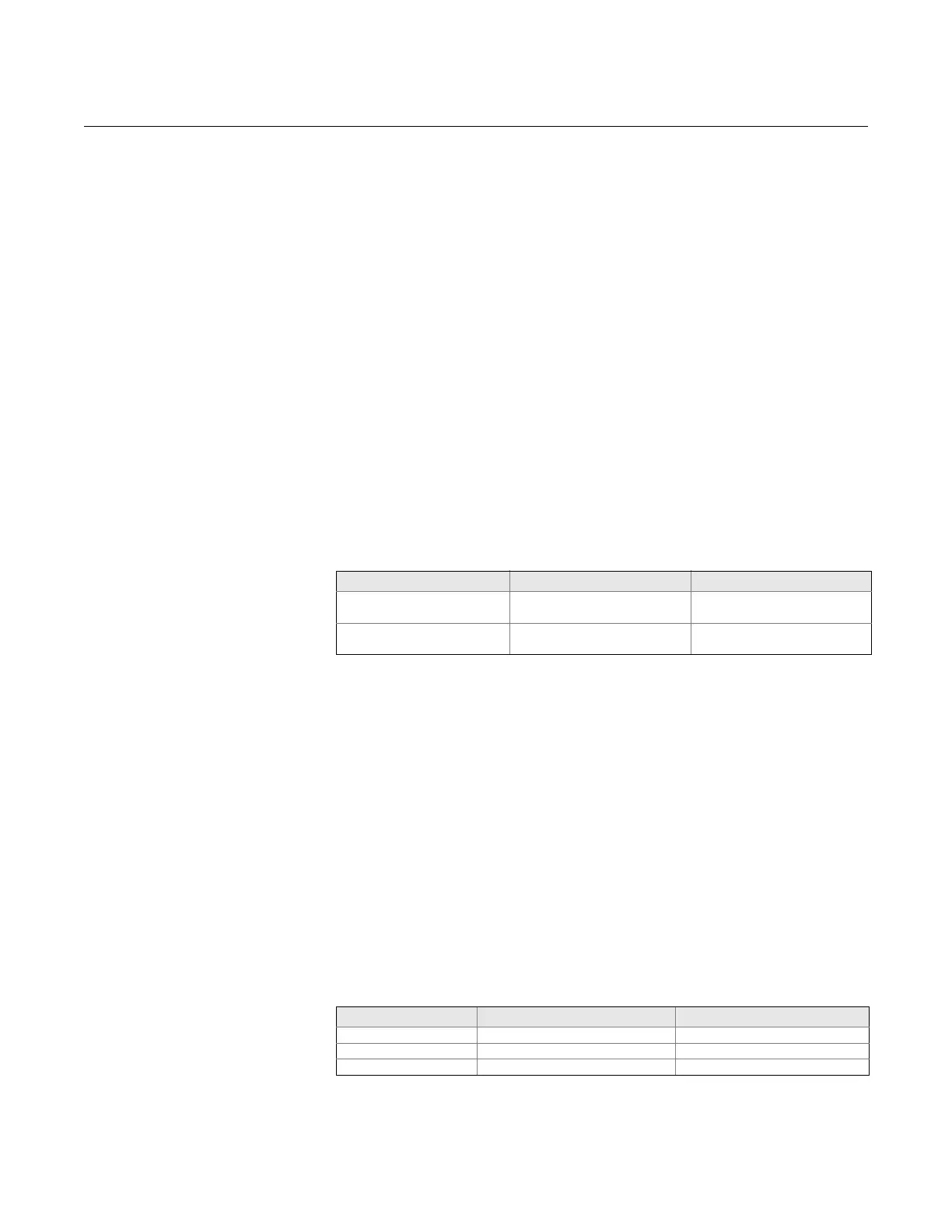
Temperature Limits
Field Communicator Connections
Field Communicator connections are permanently fixed to power/signal block.
Failure Mode
The 3144P features software and hardware failure mode detection. An
independent circuit is designed to provide backup alarm output if the
microprocessor hardware or software fails.
The alarm level is user-selectable using the failure mode switch. If failure
occurs, the position of the hardware switch determines the direction in which
the output is driven (HIGH or LOW). The switch feeds into the
digital-to-analog (D/A) converter, which drives the proper alarm output even if
the microprocessor fails. The values at which the transmitter drives its output
in failure mode depends on whether it is configured to standard,
or NAMUR-compliant (NAMUR recommendation NE 43, 2003) operation. The
values for standard and NAMUR-compliant operation are as follows:
Table A-2. Operation
Parameters
(1) A 2% variation of the transmitter mA output is allowed before a safety trip. Trip values in the
DCS or safety logic solver should be derated by 2%.
Description Operating Limit Storage Limit
Without LCD Display –40 to 185 °F
–40 to 85 °C
–60 to 250 °F
–50 to 120 °C
With LCD Meter –4 to 185 °F
–20 to 85 °C
–50 to 185 °F
–45 to 85 °C
Standard
(1)
(1) Measured in milliamperes
NAMUR-Compliant
(1)
Linear Output: 3.9 I 20.5 3.8 I 20.5
Fail HIGH: 21.75 I 23 (default) 21.5 I 23 (default)
Fail Low: I 3.75 I 3.6