Reference Manual
00809-0100-4021, Rev FB
August 2011
Rosemount 3144P
3-28
HART
Hot Backup
To enable the Hot Backup feature of a 3144P transmitter with dual-sensor
option operating in conjunction with the HART Tri-Loop, ensure that the
output units of the sensors are the same as the units of the HART
Tri-Loop. Use any combination of RTDs or thermocouples as long as the
units of both match the units of the HART Tri-Loop.
Using the Tri-Loop to Detect Sensor Drift Alert
The dual-sensor 3144P transmitter sets a failure flag (through HART)
whenever a sensor failure occurs. If an analog warning is required, the HART
Tri-Loop can be configured to produce an analog signal that can be
interpreted by the control system as a sensor failure.
Use these steps to set up the HART Tri-Loop to transmit sensor failure alerts.
1. Configure the dual-sensor 3144P variable map as shown.
2. Configure Channel 1 of the HART Tri-Loop as TV (differential
temperature). If either sensor should fail, the differential temperature
output will be +9999 or –9999 (high or low saturation), depending on the
position of the Failure Mode Switch (see “Alarm Switch (HART)” on
page 2-4).
3. Select temperature units for Channel 1 that match the differential
temperature units of the transmitter.
4. Specify a range for the TV such as –100 to 100 °C. If the range is large,
then a sensor drift of a few degrees will represent only a small percent of
range. If Sensor 1 or Sensor 2 fails, the TV will be +9999 (high
saturation) or –9999 (low saturation). In this example, zero is the
midpoint of the TV range. If a T of zero is set as the lower range limit
(4 mA), then the output could saturate low if the reading from Sensor 2
exceeds the reading from Sensor 1. By placing a zero in the middle of
the range, the output will normally stay near 12 mA, and the problem will
be avoided.
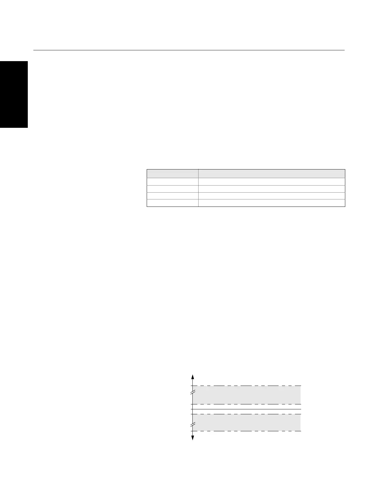
5. Configure the DCS so that TV –100 °C or TV 100 °C indicates a
sensor failure and, for example, TV –3 °C or TV 3 °C indicates a drift
alert. See Figure 3-9.
Figure 3-9. Tracking Sensor Drift
and Sensor Failure with
Differential Temperature
Variable Mapping
PV Sensor 1 or Sensor Average
SV Sensor 2
TV Differential Temperature
QV As Desired
3 °C
0 °C
–3 °C
100 °C
Sensor Drift
Sensor Drift
Sensor Failure
(Failure Mode Switch HIGH)
DIFFERENTIAL
TEMPERATURE
Sensor Failure
(Failure Mode Switch LOW)
–100 °C