Hazardous Area Oxymitter 5000
9-4
Instruction Manual
IM-106-350C, Rev 2.2
July 2008
3. IMPS 4000. Use the IMPS 4000 keypad to change the InitCalX
parameter of the CHANGE PRESETS display mode from 0000 to 0001.
Refer to the IMPS 4000 Intelligent Multiprobe Test Gas Sequencer
Instruction Bulletin for more information.
4. FOUNDATION fieldbus. Use fieldbus to perform the O
2
CAL method.
5. Remote Contact. Initiate a calibration from a remote location via the
remote contact input connection provided by an IMPS 4000 or SPS
4001B. Refer to the documentation available for the control system in
use for more information.
Once a semi-automatic calibration is initiated by any of the methods
previously described, the Hazardous Area Oxymitter 5000's CALIBRATION
RECOMMENDED alarm signals an IMPS 4000 or SPS 4000 to initiate a
calibration. The sequencer sends an "in cal" signal to the control room so that
any automatic control loops can be placed in manual. Then, the sequencer
begins to sequence the calibration gases.
Manual Calibration with
Membrane Keypad
Manual calibrations must be performed at the Hazardous Area Oxymitter
5000 site and will require operator intervention throughout the process.
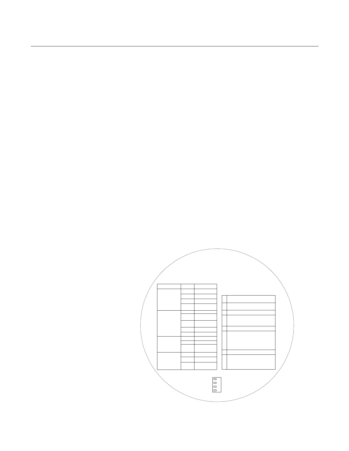
Manual calibration instructions, in condensed form, can also be found on the
inside of the right electronics housing cover (Figure 9-2).
Use the following procedure to perform a manual calibration:
1. Place control loop in manual.
2. Verify the calibration gas parameters are correct per "Calibration with
Keypad".
Figure 9-2. Inside Right Cover
SW2DIP SWITCH
LED
HEATER
O2CELL
CALIBRATION
HEATER T/C
STATUS
OPEN
SHORTED
REVERSED
HIGHHIGH
TEMP
HIGHCASE
TEMP
LOW TEMP
HIGH TEMP
OPEN
BAD
EPROM
CORRUPT
INVALIDSLOPE
INVALID
CONSTANT
FLASHES
1
2
3
4
1
2
OPEN
3
4
5
1
3
4
1
2
PUSHCAL
CAL LEDON
APPLY TG1
PUSHCAL
CAL LEDONSOLID
REMOVE TG1& APPLY TG2
PUSHCAL
CAL LEDONSOLID
WAIT FORFLASH
REMOVE TG2
PUSHCAL
1
2
3
4
5
6
7
ALARMS
MANUAL
CALIBRATION
CAL LEDONFOR
PURGE TIME
WAIT FORFLASH
CAL LEDOFF
PUSHCAL
CAL LEDFLASH
2FLASH-VALIDCAL
3FLASH-INVALIDCAL
8
PLACECONTROL LOOP
INMANUAL
IFCAL LEDON
GO TOSTEP 2
*
*
3
LAST CAL
FAILED
A/DCOMM
ERROR
38740018
OFF
ON
NOT USEDNOT USED
NOT USEDNOT USED
NOT USEDNOT USED