Hazardous Area Oxymitter 5000
4-2
Instruction Manual
IM-106-350C, Rev 2.2
July 2008
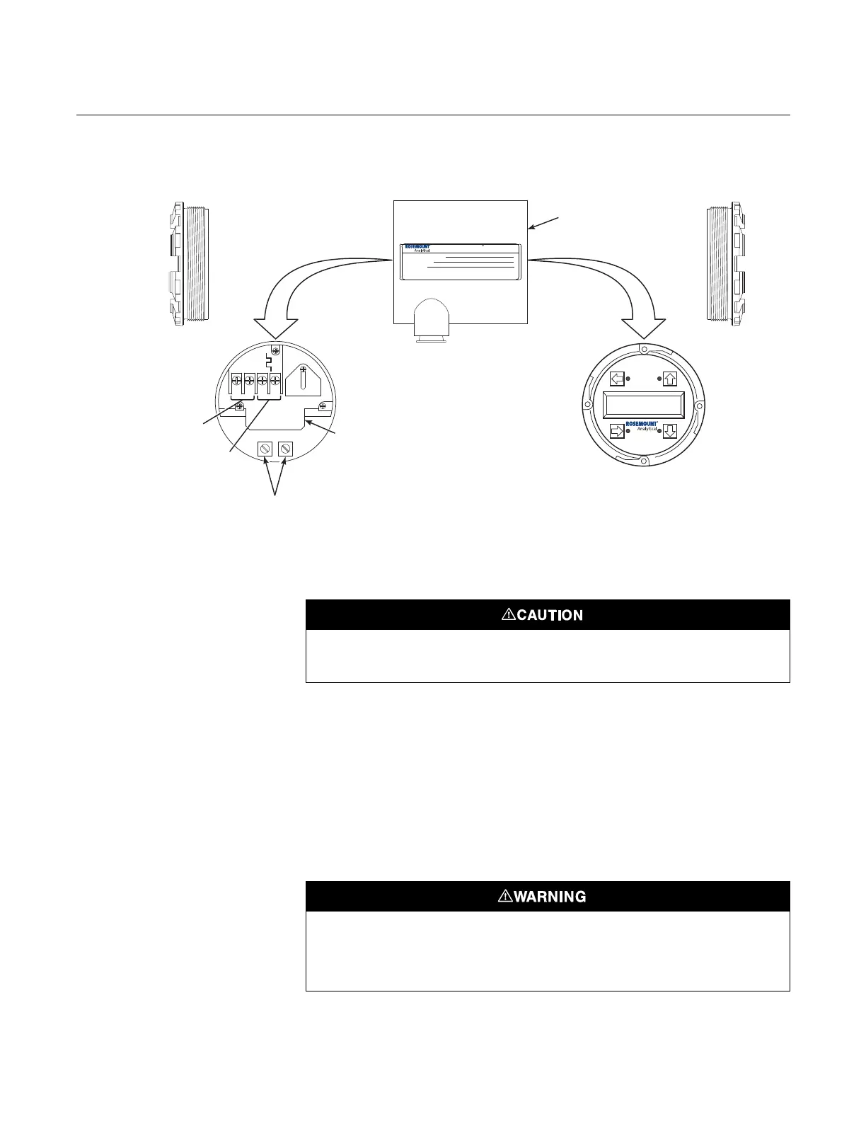
Figure 4-1. Electronics Housing
Terminals with LOI
Hazardous Area
Oxymitter 5000
Configuration
Located on the microprocessor board, the top board, is a switch that controls
the simulate enable status of the Oxymitter 5000 (Figure 4-2). To access this
switch, the LOI module must be removed. To allow the Oxymitter to be placed
in simulation mode, place position two of SW2 in the ON position. Once the
Oxymitter has been set to simulate mode, switch position two of SW2 to the
OFF position to remove the Oxymitter from simulate mode. Note that SW2
does not actually place the Oxymitter in simulate mode, it only allows the
Oxymitter to be placed into simulate mode through the fieldbus interface.
Positions 1, 3 and 4 of SW2 are not used, and should remain in the OFF
position.
AC L1
AC N
+
+
-
-
500 VA
SERIAL NO.
TAG NO.
OXYMITTER 5000
WATTS:VOLTS:
FUSE:LINEOUTPUT:
Rosemount AnalyticalInc.
Solon,OH44139
85-264 VAC 48-62 Hz
TM
800-433-6076
4-20 mA
R
5 Amps
TM
HART
SMART FAMILY
FieldbusDigital
Signal
LogicI/O
GroundLugs
Terminal
Block
Hazardous Area
Oxymitter5000
Electronics
Housing
38740034
LOI
Remove power before changing defaults. If defaults are changed under power, damage to
the electronics package may occur.
Typically, the probe's sensing cell, in direct contact with the process gases, is heated to
approximately 1357°F (736°C). The external temperat ure of the probe body may exceed
842°F (450°C). If operating conditions also contain high oxygen levels and combustible
gases, the Oxymitter 5000 may self-ignite.