Hazardous Area Oxymitter 5000
4-4
Instruction Manual
IM-106-350C, Rev 2.2
July 2008
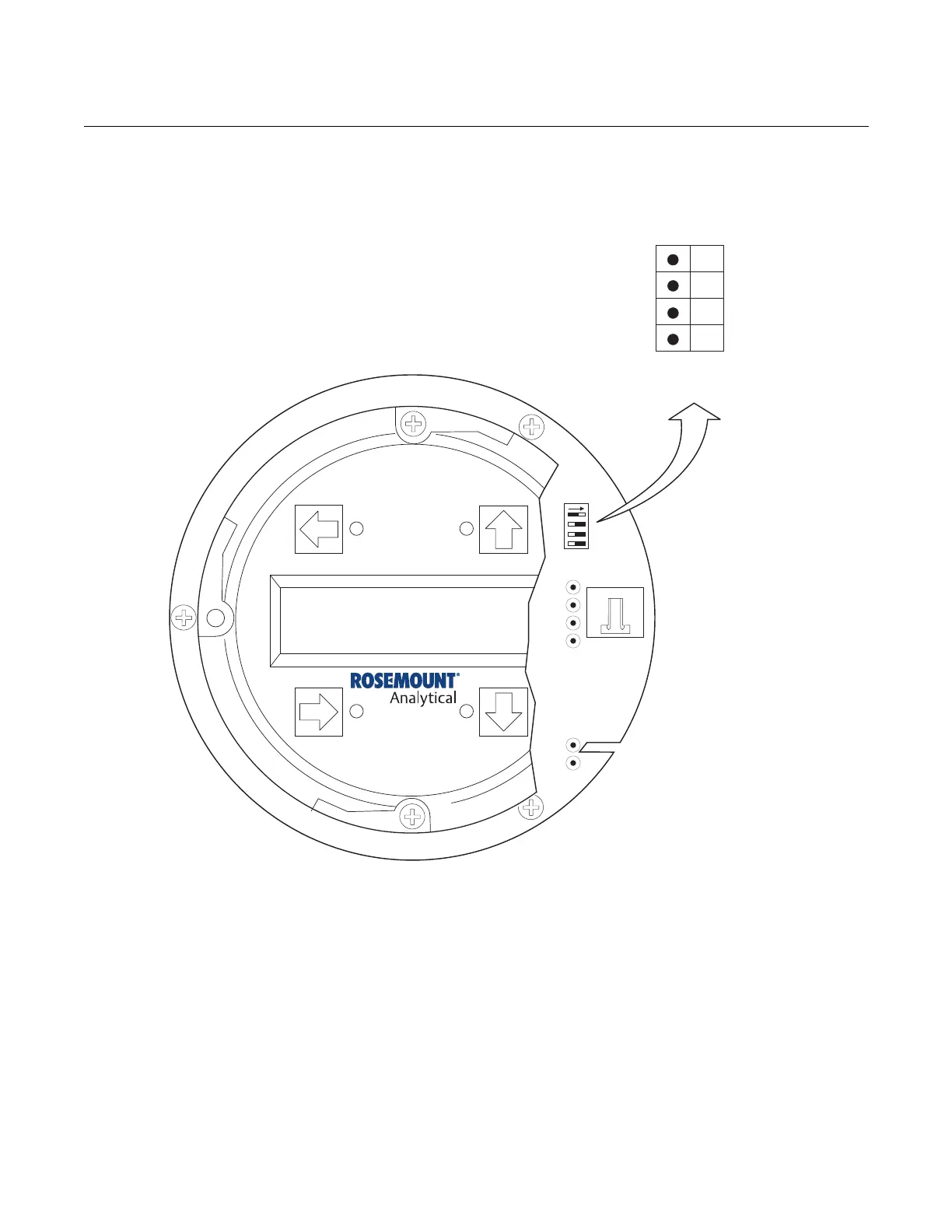
Figure 4-2. Defaults - Hazardous
Area Oxymitter 5000 with LOI
LOGIC I/O
This two-terminal logic contact can be configured either as a solid-state
relay-activated alarm or as a bi-directional calibration handshake signal to an
IMPS 4000 or SPS 4001B. The configuration of this signal depends on the
setting of the LOGIC I/O PIN MODE via FOUNDATION fieldbus or LOI. The
ten different modes available are explained in Table 4-1.
Alarm
When configured as an alarm, this signal alerts you to an out-of-spec
condition. The output is +5 Vdc in series with a 340 ohm resistor.
For optimum performance, Emerson Process Management recommends
connecting the output to a Potter & Brumfield 3.2 mA DC relay (P/N
R10S-E1Y1-J1.0K).
SW2
1
2
3
4
TP1
J1
TP2
TP3
RED
YEL
GRN
ORG
TP4
TP5
TP6
NotUsed
OFF
Default
position
(Ex-factory)
Simulate
Enable
38740035
NotUsed
NotUsed
NotUsed
ON
NotUsed
NotUsed