Hazardous Area Oxymitter 5000
6-6
Instruction Manual
IM-106-350C, Rev 2.2
July 2008
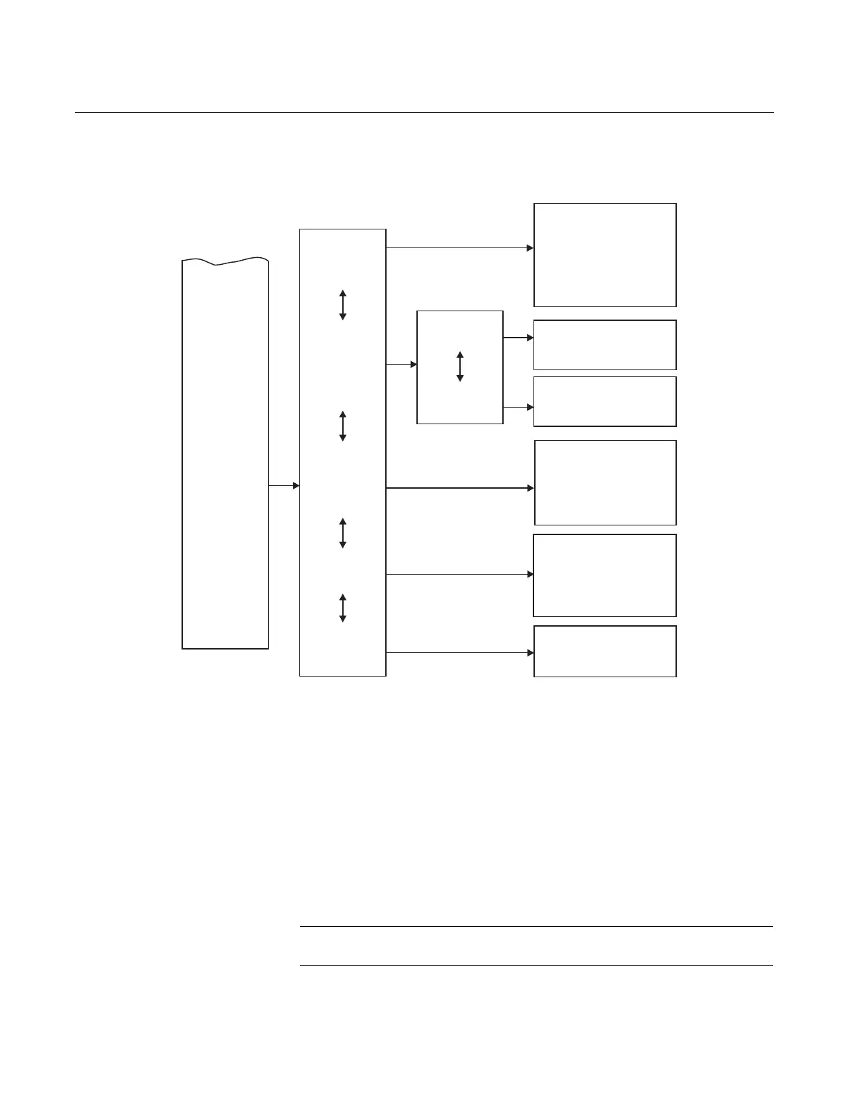
Figure 6-4. Local Operator
Interface Menu Tree
(Sheet 2 of 2)
HAZARDOUS AREA
OXYMITTER 5000 SETUP
AT THE LOI
In setting up the Hazardous Area Oxymitter 5000 from the LOI, it is best to
start at the SYSTEM/Calibration Setup menu, Figure 6-4.
SYSTEM/Calibration Setup
O2 Gas #1 - Enter the high or low cal gas value (the order is not important).
O2 Gas #2 - Enter the second cal gas value.
NOTE
Refer to Section 9: Maintenance and Service, for calibration instructions.
SYSTEM
O2Gas1
O2Gas2
O2-ResetVals
O2OutTracks
O2CalIntervl
O2-NextCal
GasTime
PurgeTime
AutoCalib?
_____%
_____%
Yes/No
Yes/No
____H
____H
___Sec.
___Sec.
Yes/No
O2Type
O2Range
O2 AlarmLeve
_______
______%
l _____mA
DoO2Trim
CalibSetup
Input/Output
Parameters
Status
Software
(CONTINUEDFROM
SHEET 1)
Analog
Digital
NOTE
Incolumnfourofthismenu,theselectionsin areuserconfigurable. textselectionsare
procedures;relatedinstructionsaredisplayedontheLOI. Allotherparametersaredisplayonly.
Italics Bold
Version xxx
Checksum xxx
BuildNumber xxx
BuildDate xxxxxx
TestCode xx
SWErrFile xx
SWErrLine xx
Alarms __________
PIDParameters 115/220
Yes/No
(Cal.requiredafterreset)
ResetDevice?
O2Slope
O2Constant
O2T90Time
AutoTune?
LockoutTime
RevertTime
Luminance
____mV/D
____mV
0:00
Yes/No
0:00
0:00
______
LogicIOMode
LowO2 Alarm
ForceOutput
See Table4-1
Seepara.9-3b
InputState _______
_______
38740011