Hazardous Area Oxymitter 5000
8-4
Instruction Manual
IM-106-350C, Rev 2.2
July 2008
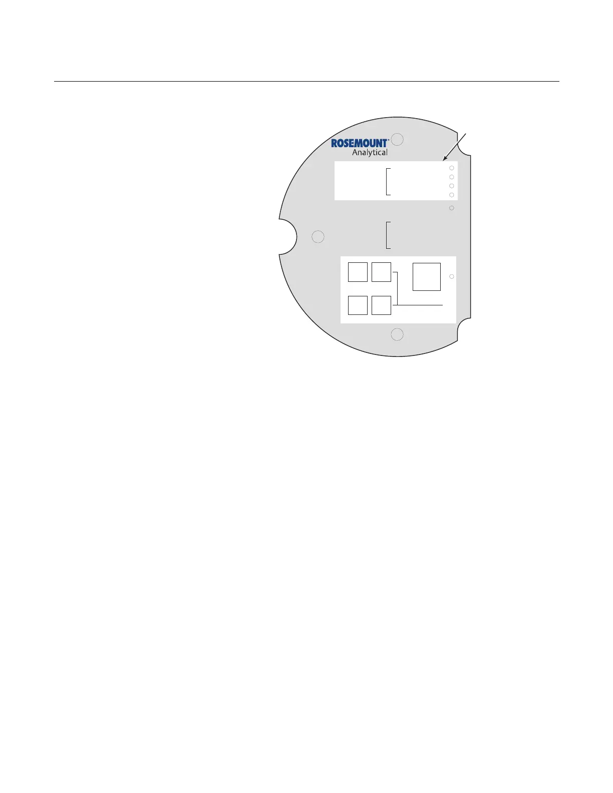
Figure 8-2. Diagnostic LEDs
ALARM CONTACTS
If autocalibration is not utilized, a common bi-directional logic contact is
provided for any of the diagnostic alarms listed in Table 8-1. The assignment
of alarms which can actuate this contact can be modified to one of seven
additional groupings (mode 0 through mode 7) listed in Table 3-1.
The logic contact is self-powered, +5 VDC, with a 340 ohm series resistance.
An interposing relay will be required if this contact is to be utilized to
annunciate a higher voltage device, such as a light or horn. An interposing
relay may also be required for certain DCS input cards.
A Potter & Brumfield R10S-E1Y1-J1.0K 3.2 mA DC or an equal interposing
relay will be mounted where the contact wires terminate in the control/relay
room.
If autocalibration systems are utilized, the bi-directional logic contact is
utilized as a "hand-shake" signal between the autocalibration system (SPS
4001B or IMPS 4000) and is unavailable for alarming purposes. The following
additional contacts are provided through the autocalibration systems:
DIAGNOSTIC
ALARMS
TEST
POINTS
HEATER T/C
HEATER
02 CELL
CALIBRATION
CALIBRATION RECOMMENDED
02 CELL mV +
02 CELL mv -
HEATER T/C +
HEATER T/C -
INC INC
DEC DEC
HIGH
GAS
LOW
GAS
CAL
TEST GAS +
PROCESS -
% 02
Diagnostic
LEDs
38740043