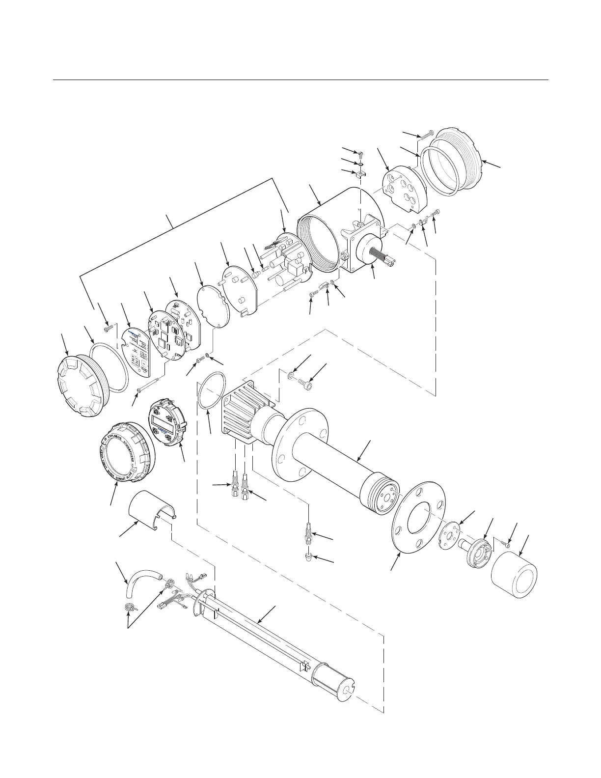
Figure 9-3. Hazardous Area Oxymitter 5000 with Integral Electronics - Exploded View
38740060
39
23
38
2
Note: Notallpartsshown.
30
29
29
29
36
25
24
26
27
28
37
22
21
1A
Note: TheElectronic Assembly,item2,
consistsofitems3through10,
anditems31-34.
17A
1. BlindCover
1A. WindowCover
2. Electronic Assembly
3. Screw
4. MembraneKeypad
4A. LOIModule
5. MicroprocessorBoard
6. AnalogBoard
7. FuseCap
8. Fuse
9. PowerSupplyBoard
10. CaptiveScrew
11. Housing
12. Screw
13. LockWasher
14. CableClamp
15. TerminalBlock
16. CaptiveScrew
17. BlindCover
17A. O-Ring
18. Screw
19. CoverLock
20. CaptiveWasher
21. Washer
22. Screw
23. Probe Tube Assembly
24. Gasket
25. CorrugatedSeal
26. CellandFlange
Assembly
27. RetainerScrew
28. Flame Arresterwith
SnubberDiffuser
29. Flame
ArrestorFitting
30. Cap
31.Screw
32.Washer
33.FieldbusOutputBoard
34.FieldbusIsolatorBaord
35. O-Ring
36. HeaterStrut Assembly
37. TubeClamp
38. Silicon Tube
39. StrutPressureClamp
35
9
7
8
18
18
20
20
19
19
11
12
13
14
15
16
Integral
Electrical
Barrier/
Feedthrough
17
4A
17A
10
3
4
6
1
5
33
34
32
31

 Loading...


