Hazardous Area Oxymitter 5000
9-18
Instruction Manual
IM-106-350C, Rev 2.2
July 2008
Cell Replacement
This paragraph covers O
2
cell replacement. Do not attempt to replace the cell
until all other possibilities for poor performance have been considered. If cell
replacement is needed, order the cell replacement kit. Table 10-1.
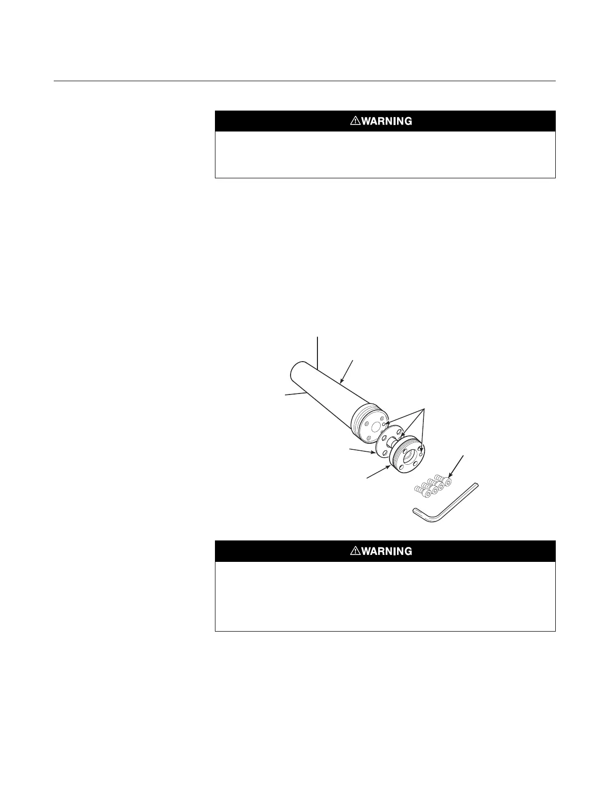
The cell replacement kit (Figure 9-9) contains a cell and flange assembly,
corrugated seal, setscrews, socket head cap screws, and anti-seize
compound. The items are carefully packaged to preserve precise surface
finishes. Do not remove items from the packaging until they are ready to be
used. Spanner and hex wrenches needed for this procedure are part of an
available special tools kit. Table 10-1.
Figure 9-9. Cell Replacement Kit
When working on this equipment on the laboratory bench, be aware that the Hazardous
Area Oxymitter 5000, probe tube, and flame arrestor hub can be hot [up to 300°C (572°F)]
in the region of the probe heater.
38740022
Probe Tube
(NotIncluded
inKit)
Corrugated
Seal
Celland
Flange
Assembly
CalibrationGas
Passage
SocketHead
CapScrews
Use heat-resistant gloves and clothing when removing the probe. Do not attempt to work on
these components until they have cooled to room temperature. Probe components can be
as hot as 300°C (572°F). This can cause severe burn s.
Disconnect and lock out power before working on any electrical components. There is
voltage of up to 115 VAC.