Hazardous Area Oxymitter 5000
1-4
Instruction Manual
IM-106-350C, Rev 2.2
July 2008
When the cell is at operating temperature and there are unequal oxygen
concentrations across the cell, oxygen ions will travel from the high oxygen
partial pressure side to the low oxygen partial pressure side of the cell. The
resulting logarithmic output voltage is approximately 50 mV per decade. The
output is proportional to the inverse logarithm of the oxygen concentration.
Therefore, the output signal increases as the oxygen concentration of the
sample gas decreases. This characteristic enables the Hazardous Area
Oxymitter 5000 to provide exceptional sensitivity at low oxygen
concentrations.
The Hazardous Area Oxymitter 5000 measures net oxygen concentration in
the presence of all the products of combustion, including water vapor.
Therefore, it may be considered an analysis on a "wet" basis. In comparison
with older methods, such as the portable apparatus, which provides an
analysis on a "dry" gas basis, the "wet" analysis will, in general, indicate a
lower percentage of oxygen. The difference will be proportional to the water
content of the sampled gas stream.
System Configuration
Hazardous Area Oxymitter 5000 units are available in three length options,
giving the user the flexibility to use an in situ penetration appropriate to the
size of the stack or duct. The options on length are 457 mm (18 in.), 0.91 m (3
ft), and 1.83 m (6 ft).
The electronics control probe temperature and provide an output, that
represents the measured oxygen concentration. The power supply can accept
voltages of 90-250 VAC and 48/62 Hz; therefore, no setup procedures are
required. The oxygen sensing cell is maintained at a constant temperature by
modulating the duty cycle of the probe heater portion of the electronics. The
electronics accepts millivolt signals generated by the sensing cell and
produces the outputs to be used by remotely connected devices. The output
is a FOUNDATION fieldbus digital communication signal.
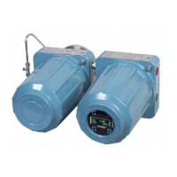
The Oxymitter 5000 transmitter is available with an integral or remote
electronics package. Two calibration gas sequencers are available to the
Hazardous Area Oxymitter 5000, but they must be installed in a
nonhazardous, explosive-free environment: the IMPS 4000 and the SPS
4001B (Figure 1-2).
Systems with multiprobe applications may employ an optional IMPS 4000
Intelligent Multiprobe Test Gas Sequencer. The IMPS 4000 provides
automatic calibration gas sequencing for up to four Hazardous Area Oxymitter
5000 units and accommodates autocalibrations based on the CALIBRATION
RECOMMENDED signal from the Hazardous Area Oxymitter 5000, a timed
interval set up via fieldbus or the IMPS 4000, or whenever a calibration
request is initiated.