Instruction Manual
IM-106-350C, Rev 2.2
July 2008
Hazardous Area Oxymitter 5000
http://www.raihome.com
Section 5 Startup and Operation of
Hazardous Area Oxymitter 5000
with Membrane Keypad
Power Up . . . . . . . . . . . . . . . . . . . . . . . . . . . . . . . . . . . . . . . page 5-1
Operation . . . . . . . . . . . . . . . . . . . . . . . . . . . . . . . . . . . . . . . page 5-2
POWER UP
Startup Display
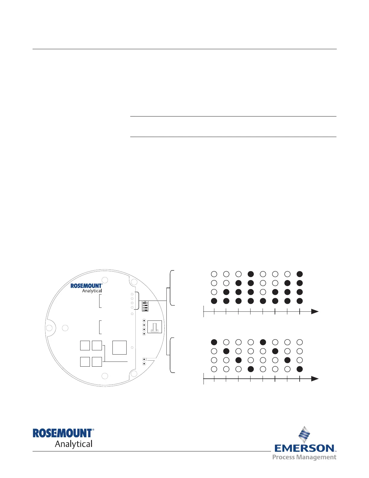
When power is applied to the probe, the cell heater turns on. It takes
approximately one half hour for the cell to heat to operating temperature. This
condition is indicated by the top four LEDs (DIAGNOSTIC ALARMS) on the
membrane keypad (Figure 5-1). Starting with the CALIBRATION LED, the
LEDs light in ascending order until all four LEDs are on. At this point, all four
turn off and the cycle starts again. This ramp cycle continues until the cell is
up to operating temperature.
Operating Display
The ramp cycle turns into a cycle where the diagnostic LEDs light in sequence
from the top to the bottom, one at a time. After the bottom LED turns on, the
sequence starts again at the top with the HEATER T/C LED (Figure 5-1).
Figure 5-1. Startup and Normal Operation
DIAGNOSTIC
ALARMS
TEST
POINTS
HEATER T/C
HEATER
O2 CELL
CALIBRATION
CALIBRATION RECOMMENDED
O2 CELL mV +
O2 CELL mv -
HEATER T/C +
HEATER T/C -
INC INC
DEC DEC
HIGH
GAS
LOW
GAS
CAL
TEST GAS +
PROCESS -
% O2
SW2
TP1
J1
TP2
TP3
RED
YEL
GRN
ORG
TP4
TP5
TP6
ON
HEATER T/C
HEATER
O CELL
2
CALIBRATION
1
2 3 4 1 2 3 4
HEATER T/C
HEATER
O CELL
2
CALIBRATION
1
2 3 4 1 2 3 4
Lightingsequenceduringnormaloperation
(Operatingdisplay)
Lightingsequenceduringwarm-up
(Startupdisplay)
38740036