Hazardous Area Oxymitter 5000
3-2
Instruction Manual
IM-106-350C, Rev 2.2
July 2008
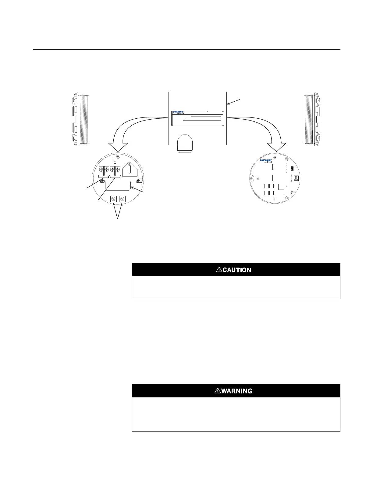
Figure 3-1. Electronics Housing
Terminals and Membrane
Keypad
Hazardous Area
Oxymitter 5000
Configuration
Located on the microprocessor board, the top board, is a switch that controls
the simulate enable status of the Oxymitter 5000 (Figure 3-2). To allow the
Oxymitter to be placed in simulation mode, place position two of SW2 in the
ON position. Once the Oxymitter has been set to simulate mode, switch
position two of SW2 to the OFF position to remove the Oxymitter from
simulate mode. Note that SW2 does not actually place the Oxymitter in
simulate mode, it only allows the Oxymitter to be placed into simulate mode
through the fieldbus interface.
Positions 1, 3 and 4 of SW2 are not used, and should remain in the OFF
position.
38740032
ACL1
ACN
+
+
-
-
500 VA
SERIAL NO.
TAG NO.
OXYMITTER 5000
WATTS:VOLTS:
FUSE:LINEOUTPUT:
Rosemount AnalyticalInc.
Solon,OH44139
85-264 VAC 48-62 Hz
TM
800-433-6076
4-20 mA
R
5 Amps
TM
HART
SMARTFAMILY
DIAGNOSTIC
ALARMS
TEST
POINTS
HEATER T/C
HEATER
02CELL
CALIBRATION
CALIBRATIONRECOMMENDED
02CELL mV+
02CELL mv-
HEATER T/C+
HEATER T/C-
INC INC
DEC DEC
HIGH
GAS
LOW
GAS
CAL
TEST GAS+
PROCESS-
%02
SW2
TP1
J1
TP2
TP3
RED
YEL
GRN
ORG
TP4
TP5
TP6
ON
FielbusDigital
Signal
LogicI/O
GroundLugs
Terminal
Block
Oxymitter5000
Electronics
Housing
Remove power before changing defaults. If defaults are changed under power, damage to
the electronics package may occur.
Typically, the probe's sensing cell, in direct contact with the process gases, is heated to
approximately 1357°F (736°C). The external temperat ure of the probe body may exceed
842°F (450°C). If operating conditions also contain high oxygen levels and combustible
gases, the Oxymitter 5000 may self-ignite.