Hazardous Area Oxymitter 5000
3-4
Instruction Manual
IM-106-350C, Rev 2.2
July 2008
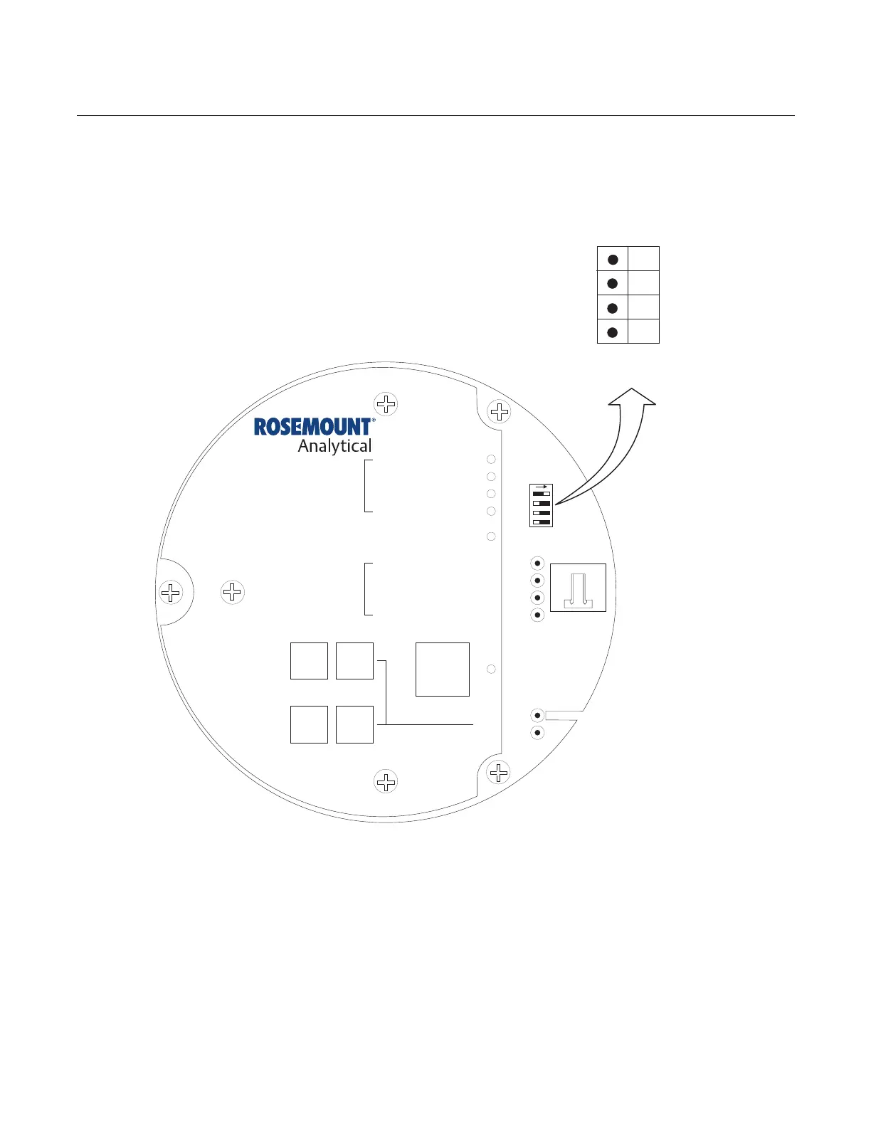
Figure 3-2. Defaults - Hazardous
Area Oxymitter 5000 with
Membrane Keypad
LOGIC I/O
This two-terminal logic contact can be configured either as a solid-state
relay-activated alarm or as a bi-directional calibration handshake signal to an
IMPS 4000 or SPS 4001B. The configuration of this signal depends on the
setting of the LOGIC I/O PIN MODE via fieldbus or LOI. The ten different
modes available are explained in Table 3-1.
Alarm
When configured as an alarm, this signal alerts you to an out-of-spec
condition. The output is +5 Vdc in series with a 340 ohm resistor.
DIAGNOSTIC
ALARMS
TEST
POINTS
HEATER T/C
HEATER
O2 CELL
CALIBRATION
CALIBRATION RECOMMENDED
O2 CELL mV +
O2 CELL mV -
HEATER T/C +
HEATER T/C -
INC INC
DEC DEC
HIGH
GAS
LOW
GAS
CAL
TEST GAS +
PROCESS -
% O2
SW2
TP1
J1
TP2
TP3
RED
YEL
GRN
ORG
TP4
TP5
TP6
ON
NotUsed
OFF ON
NotUsed
Default
position
(Ex-factory)
1
2
3
4
Simulate
Enable
38740033
NotUsed
NotUsed
NotUsed
NotUsed
 Loading...


