Instruction Manual
IM-106-350C, Rev 2.2
July 2008
6-9
Hazardous Area Oxymitter 5000
Board Temp Max - This is the maximum temperature that the electronics
has experienced over time.
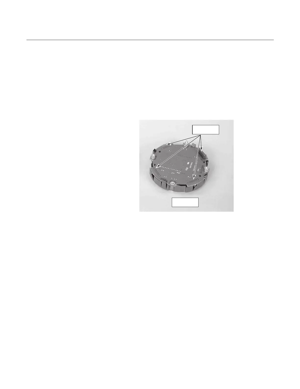
LOI INSTALLATION
The LOI connects to the top of the electronic assembly in the electronics
housing. There are four matching connectors on the back of the LOI module,
Figure 6-5, that allow the LOI to be oriented as desired by the user.
Figure 6-5. LOI Module
Connectors
OXYMITTER 5000 TEST
POINTS
Refer to Figure 6-6. System test points are located on the board below the
LOI module. Test points 1 through 6 allow you to monitor with a multimeter:
the heater thermocouple, the O
2
cell millivolt, and the process O
2
.
• TP1 and TP2 monitor the oxygen cell millivolt output which equates to
the percentage of oxygen present.
• TP3 and TP4 monitor the heater thermocouple.
• TP5 and TP6 monitor the process gas or the calibration gas parameter.
38740012
Connector
Receptacles
LOIModule
RearView