Subject to change. Roto NT IMO_347_EN_v0
.
July 2014
.
83
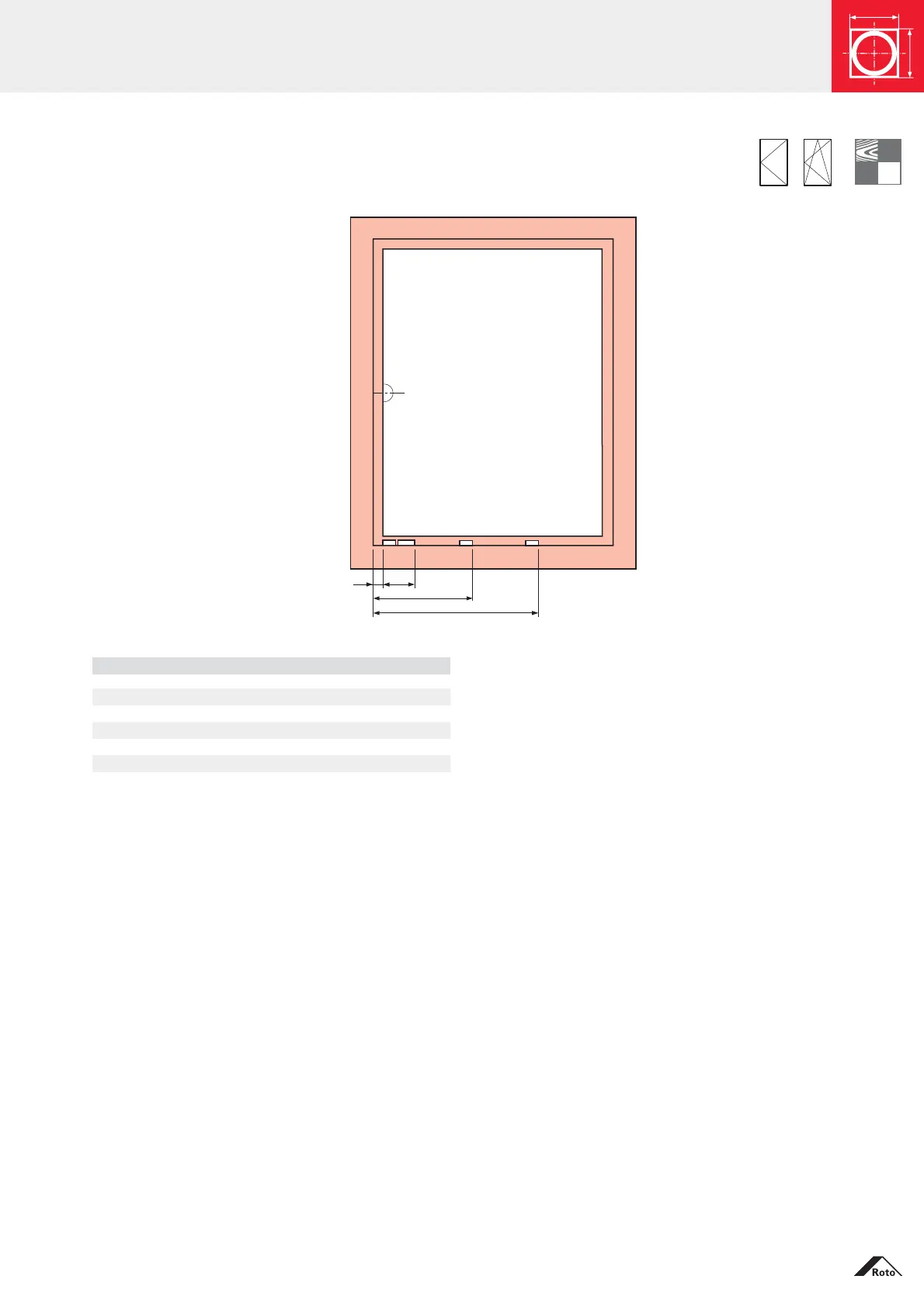
Installation drawings
Positioning of the frame components – All hinge sides
Turn-Only and Tilt&Turn – RC1 / RC2
Striker dimensions (mm)
horizontal, bottom – RC1 / RC2
24 86.5
CLH1
CLH1
Multipart centre lock, horizontal, Hinge side K
SRW / mm CLH1 CLH2
see parts lists – 258 CL 200 V
RC1 / RC2 458 – CL 400 CON
– 462 CL 400 V
– 658 CL 600 V
658 858 CL 600 CON, CL 200 (CON)
658 1062 CL 600 CON, CL 400