82
.
July 2014
.
IMO_347_EN_v0 Roto NT Subject to change.
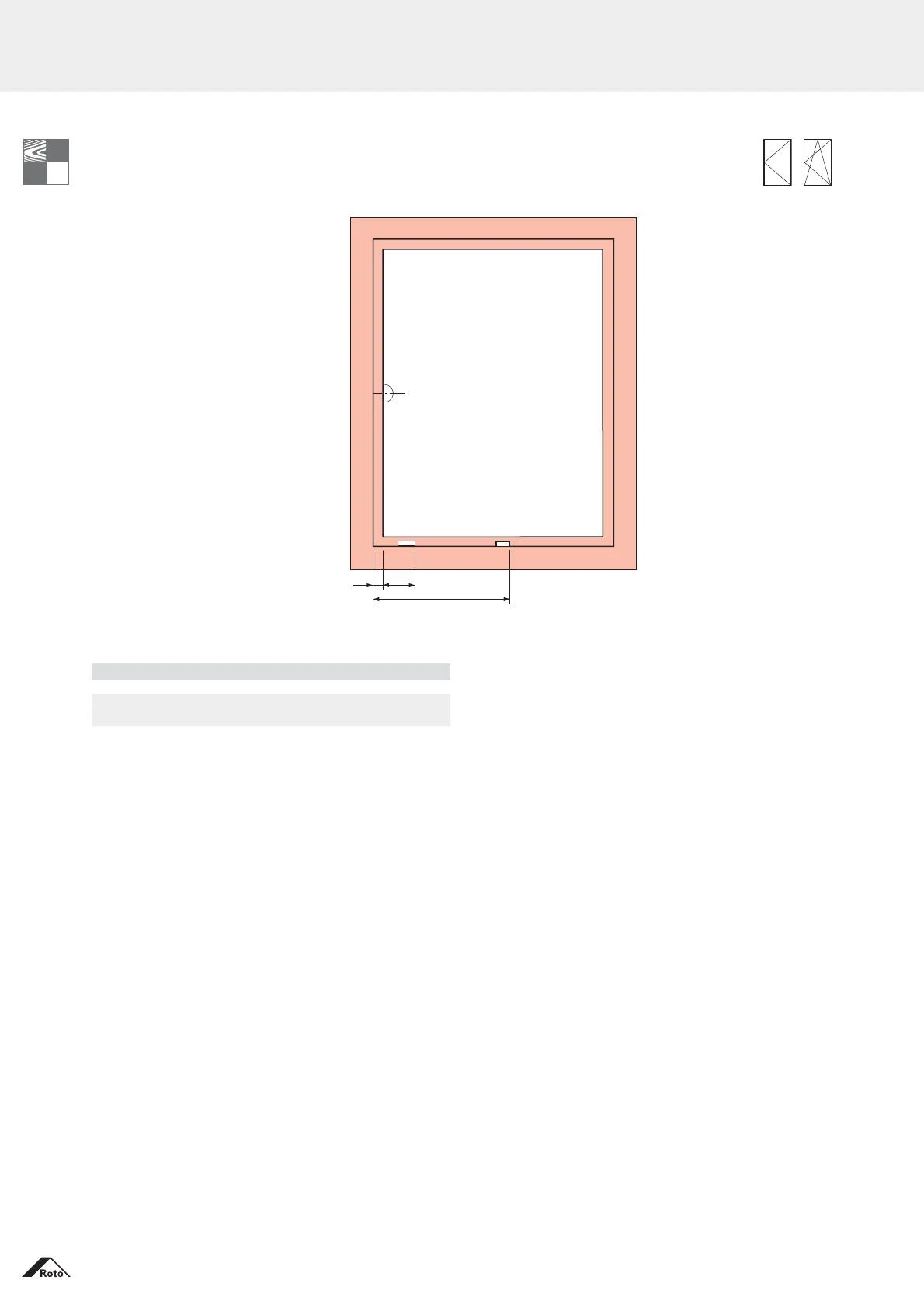
Installation drawings
Positioning of the frame components – All hinge sides
Turn-Only and Tilt&Turn – Basic security
Striker dimensions (mm)
horizontal, bottom – Basic security
LMD = Lifting mishandling device BC = Bullet catch
24 86.5
Multipart centre lock, horizontal
SRW / mm CLH1
see parts lists
Basic security
658 CL 600
CLH1