Table 10 – 4-pin male circular ConXall
3.7.7 Blue Sign Connection
If the blue sign switch should be used, the parameter “External Switch” must be
configured to “Blue Sign” in Misc. Interface view accessed from Main Menu Config
Interfaces Miscellaneous.
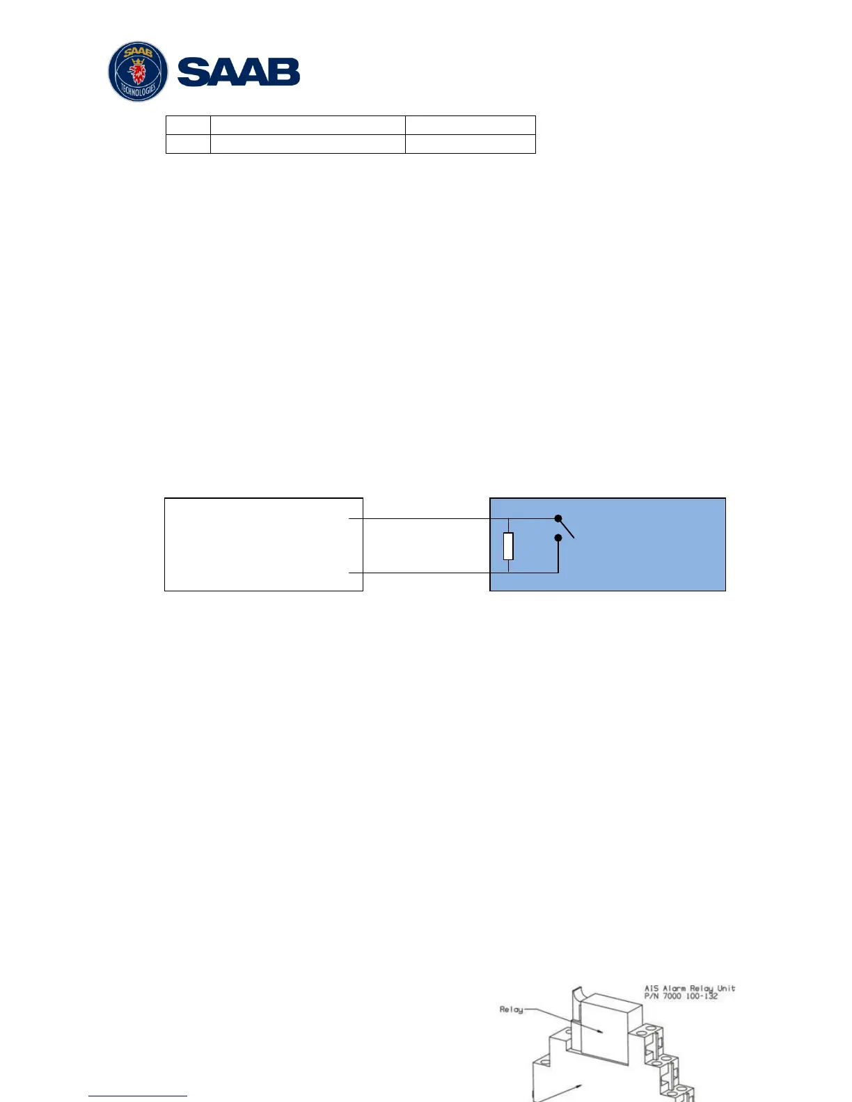
The status of the blue sign can be controlled by input on the brown and orange wires of
the R5 Power Cable.
The status of the Blue Sign will be read by the R5 SOLID and output on the VHF data
link when operating in “Inland Mode” (see section 4.4.16 for more details). Connect the
blue sign switch to pin 3 (brown wire) and pin 4 (orange wire) of the R5 Power Cable
together with an external parallel resistor. When the switch is open, blue sign will be
off. When the switch is closed, blue sign will be on.
The external resistor value depends on the power supply voltage the R5 SOLID is
using:
12V: 2.2kΩ resistor, 10% tolerance
24V: 10kΩ resistor, 10% tolerance
3.7.8 Silent Switch
It is possible to connect a silent switch to the R5 SOLID to quickly turn off
transmissions.
If a silent switch is to be used, the parameter “External Switch” must be configured to
“Silent Switch” in Misc. Interface view accessed from Main Menu Config
Interfaces Miscellaneous.
The silent switch should be connected in the same way as the blue sign switch.
However, the external resistor may be omitted for the silent switch.
When the circuit is closed (brown and orange wires connected with each other), the R5
SOLID will transmit as normal. When the circuit is open, the R5 SOLID will be
completely silent.
3.7.9 Alarm Relay
It is required that the AIS alarm output (relay) is connected to an audible alarm device
or the ship’s alarm system, if available.
Alternatively, the ship’s BIIT alarm system may use the alarm messages output on the
AIS Presentation Interface (PI) provided the alarm system is AIS compatible. The AIS
Alarm Relay is either mounted on a DIN mounting rail or direct on the wall.
The alarm relay wires have the following colour codes in the 26-pole R5 SOLID signal
cable: