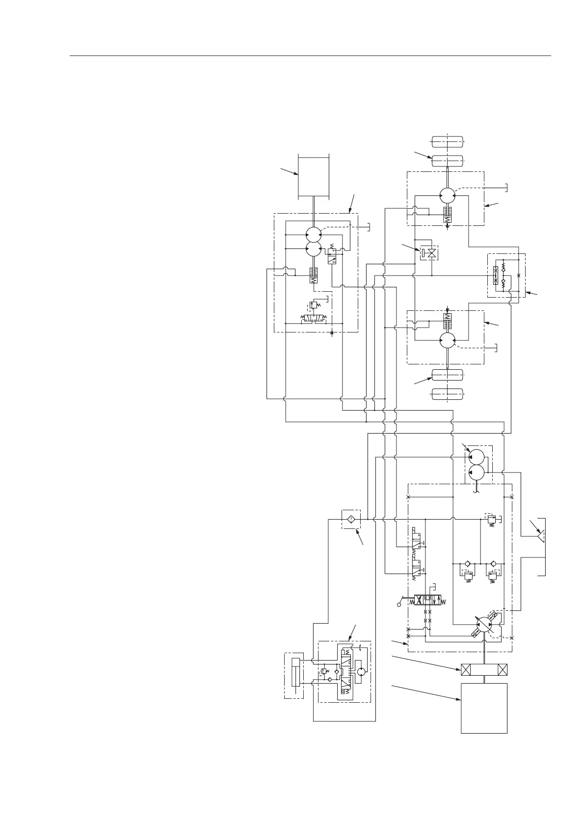
Circuit protection against excessive
pressure
・Multi-function valve (c) fitted in the
propulsion pump relieves the circuit
pressure if it exceeds the setting of
the valve, preventing damage to the
circuit.
Charge circuit
・The propulsion ciruit is of a closed
loop circuit. To prevent negative
pressure from building up in the low
pressure line (pump inlet line) due to
a leak in the high pressure line
(pump outlet line), the charge check
valve built in multi-function valve (c)
feeds oil into the low pressure line to
supply a deficiency.
・In the charge ciruit, steering/charge
pump (4) flow is fed into steering
valve (Orbitrol) (11), then the full flow
goes to propulsion pump (3) via line
filter (12) irrespective of the steering
wheel operation. When the F-R lever
is in the neutral position, charge
relief valve (d) opens to make the
steering line lead to the tank. When
travelling, the pressure in the high
pressure line actuates flushing valve
(i) so that the oil in the low pressure
line leads to the tank through valves
(i) and (j). To prevent charge relief
valve (d) from opening while
travelling, the pressure setting of
valve (d) is set higher than that of
valve (j).
Differential lock circuit (TW352, TW502)
・In normal travelling, differential
function is automatically achieved by
regulating the oil flow by means of
the orifice provided inside differential
lock valve (13).
・If rear wheels on one side begin
skidding, differential lock valve (13)
feeds more oil to the wheels on the
other side which are not skidding.
 Loading...