2-034
Description and Operation of Hydraulic System
Speed selection
*
See hydraulic circuit diagrams on pages 2-032 and 2-033.
・
When speed selector solenoid valve (f) becomes energized, oil from the charge circuit is fed into the
speed selection port of front propulsion motor (cam motor) (5) to actuate speed selector valve (g).
・With valve (g) actuated, oil that has been fed into six of twelve ports of distributor (11) while the
machine is running at ‘Low speed’ changes its direction of flow to flow into three ports alone. This
provides ‘High speed’.
*
See ‘Description and operation of cam motor’, page 2-023.
・Compared with the amount of hydraulic fluid required for the motor output shaft to make one turn
at ‘Low speed’, the motor needs only half the amount if ‘High Speed’ is selected. This doubles the
rotating speed of the motor output shaft. The pump is feeding constant quantity of fluid.
・Upon selecting ‘High speed’, the front motor runs faster, because amount of oil fed to the front
motor per shaft rotation decreases, increasing the amount of oil to the rear motor to let it run
faster. As a result, the whole motors gain speed so that the amount of oil needed for both the front
and rear motors balance. At this time, they operate at their maximum speed according to the
angular postion of the pump swashplate.
★ Reversely, when shifting from ‘High speed’ to ‘Low speed’, the amount of fluid that the front
propulsion motor draws per rotation is doubled.
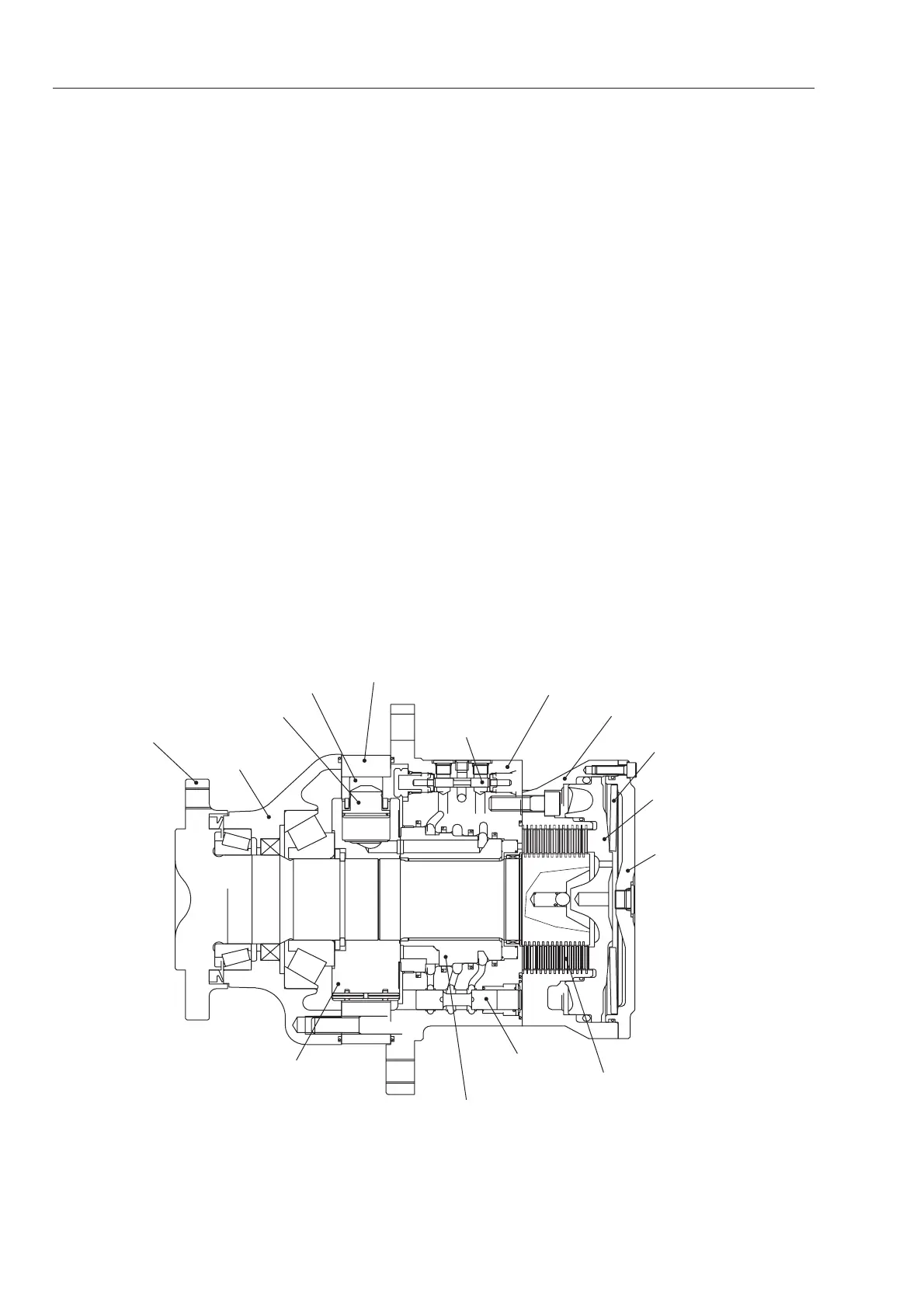
1. Output flange
2. Housing
3. Pistons
15. Rollers
5. End cap
6. Brake housing
7. Brake spring
8. Brake piston
9. Brake cover
14. Brake discs
10. Cylinder block
12. Speed selector
13. Flushing
 Loading...