4-004
How to Use Fault Diagnosis Flow Chart
3. How to Use Fault Diagnosis Flow Chart
1. Fault diagnosis code numbers
1) Electric system: E-01 to E-09
2) Hydraulic and mechanical systems: H-01 to H-09
2. How to use the fault diagnosis flow chart
q Fault diagnosis code number and fault symptom
On top of the flow chart are code number and fault symptom.
w General precautions
Under the code number and fault symptom are precautions with mark
★. Take necessary
measures as instructed by these precautions when making the inspection described in each
checking instruction box (□).
e Sub classification
To make dignosis easier or simplify the flow chart, fault symptom is subclassified. Ex. a) Starter
does not run.
r How to make diagnosis
・
Each box (□) contains a diagnosis procedure. Depending upon the result inspection or
measurement, proceed to YES or NO line.
・
Normally, if the result is YES then proceed to the upper line. If NO then go to the lower line.
★ The number above each box (□) is a reference number. It does not mean a sequence in
which diagnosis procedure should proceed.
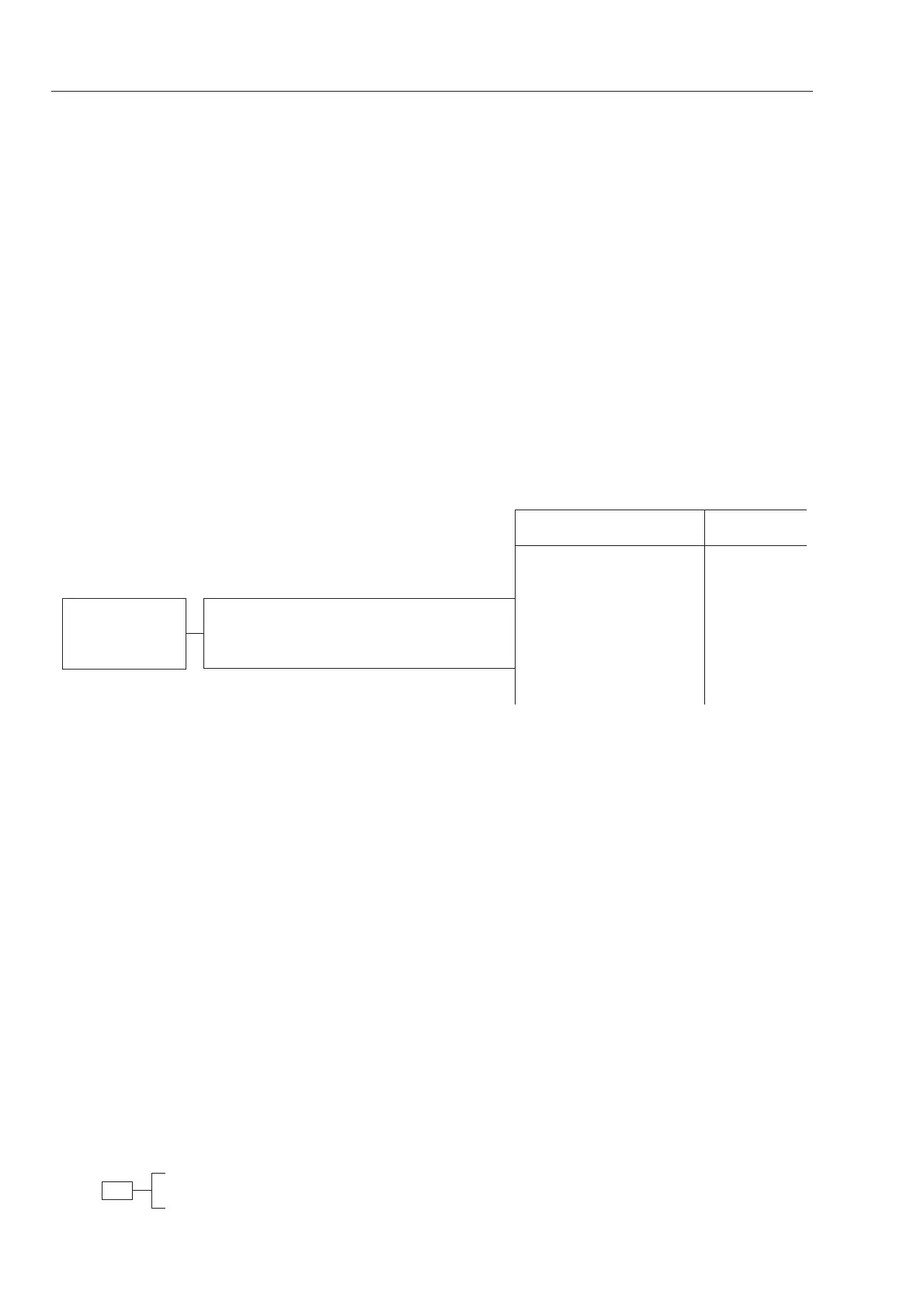
Example
q E-10 Headlamps do not work
w ★ It is assumed that other electric circuits are normal.
★ Take the voltage measurement with the starter switch ON.
e a) Tail lamps and work lamps are also faulty.
r
connected.
wire.
Renew.
 Loading...