-13-
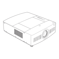
z Cabinet Top, Front, R/C Board removal
Mechanical Disassembly
Mechanical disassembly should be made following procedures in nu-
merical order.
Following steps show the basic procedures, therefore unnecessary step
may be ignored.
Caution:
The parts and screws should be placed exactly the same position as the
original otherwise it may cause loss of performance and product safety.
Screws Expression
(Type Diameter x Length) mm
T type M type
A (T3x10)x5
Cabinet front
R/C Board
Fig.1
B (M2.5x6)x2
Cabinet top
D (M2.5x6)
E (T2x6)X2
1. Remove 5 screws A(T3x10) to remove the cabinet top.
2. Remove 2 screws B(M2.5X6) and 2 screws C(T3x8) to
remove the Cabinet front.
3. Remove screw D(M2.5x6) and 2 screws E(T2x6) to
remove the Cabinet front shield.
4. Remove screw F(T2x8) to remove the R/C Board.
Control Buttons
C (T3x8)x2
A
A
A
A
F (T2x8)
B
C
E
Cabinet front shield
Spacer Lens
Decoration LED
 Loading...