-63-
Troubleshooting
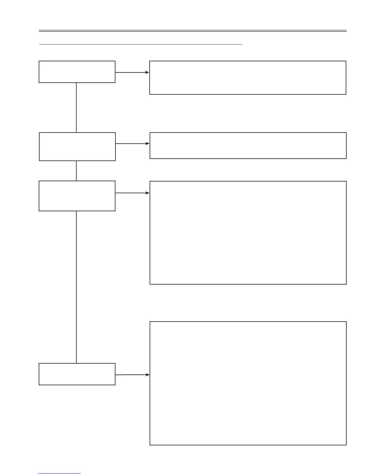
No Picture
No picture with all of
input sources
Check signal processing stage and LCD driving stage;
Check RGB S&H signals at test points TP35B, TP35G, TP35R.
Check power supply circuit S15.5V and peripheral circuit.
Check ICs IC501, IC531, IC561, IC401, IC301 and peripheral circuits.
Check HDMI interface stage;
Check IC7001<HDMI Driver> and peripheral circuit.
No picture with HDMI
input source only
No picture with PC input
source only
Yes
No
No
No
Check following steps.
Check AV source selecting and decoding stage;
S-Video source
Check S-video signal (Y/C).
S-C signal is applied to pin 108 of IC301<Scaler>, and S-Y signal is
applied on pin 318 of IC301.
S_SW signal (S-VIDEO:L) is input to pin 36 of IC301<
Scaler
>.
Composite video source
Check composite video signal (Video).
The composite video signal is applied to pins 109 of IC301 <Scaler>.
Component source
Check component signal(YCbCr).
SOG1 signal is applied to pin 315 of IC301<Scaler>, Y signal is applied
to pin 106 of IC301<Scaler>, Cr signal is applied to pin 214 of
IC301<Scaler> and Cb signal is applied to pin 215 of IC301<Scaler>.
No picture with video
input sources
Yes
Check PC source stage;
Computer source
Check RGB signals on PC1.
R1 signal is applied to pin 7 of IC2201<AD Converter>, G1 signal is
applied to pin 12 and B1 signal is applied to pin 19 of IC 2201.
HV sync signals are applied to pins 33 and 44 of IC2201<AD
Converter> as the HS1 and VS1 signals.
Check RGB signals on PC2 .
R2 signal is applied to pin 22 of IC2201<AD Converter>, G2 signal is
applied to pin 24 and B2 signal is applied to pin 28 of IC 2201.
HV sync signals are applied to pins 34 and 45 of IC2201<AD
Converter> as the HS2 and VS2 signals.
Yes
Yes
 Loading...