-22-
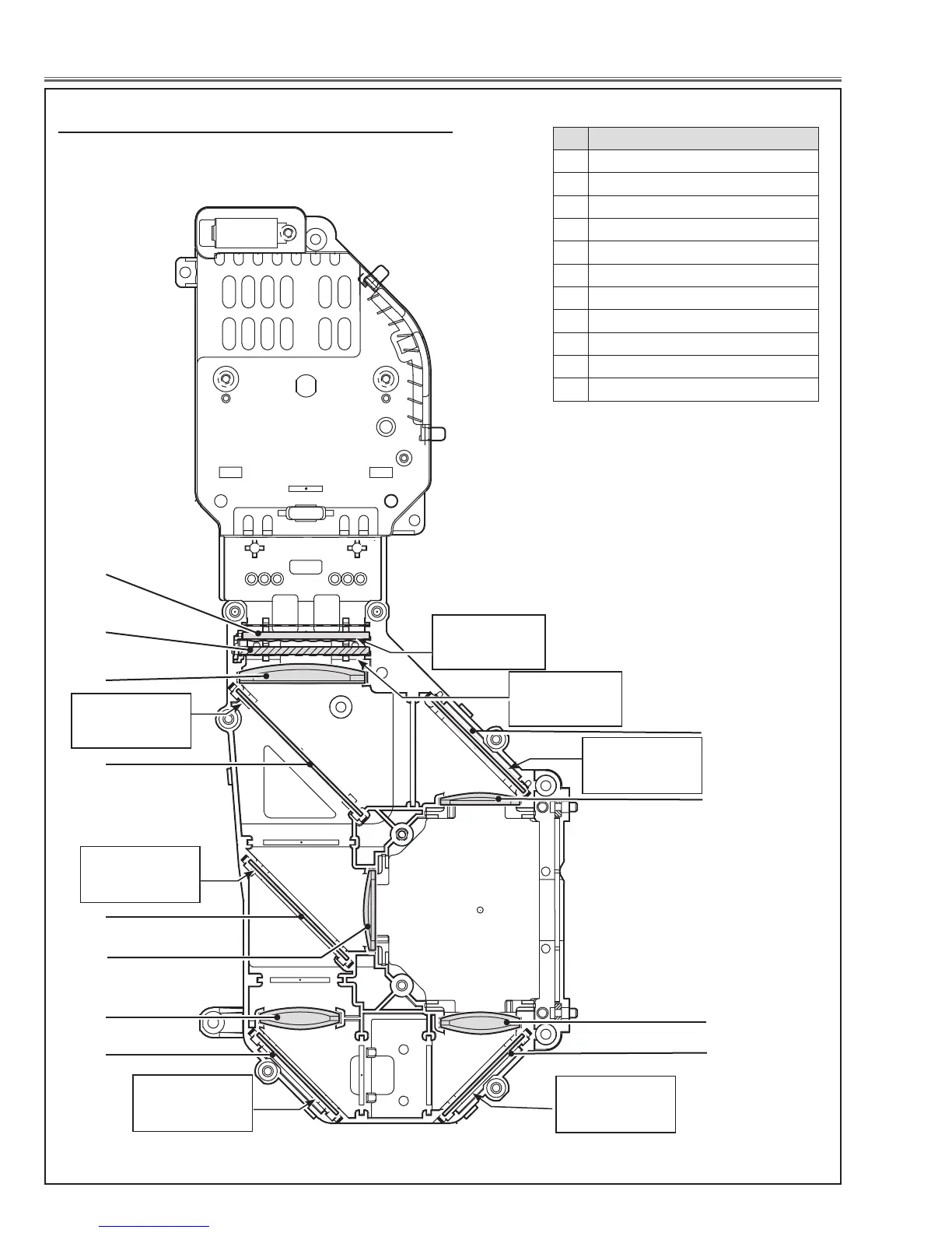
Optical Parts Disassembly
5
9
Fig.7
1
6
10
When mounting or assembling the optical parts in the op-
tical unit, the parts must be mounted in the specified loca-
tion and direction as shown in figure below.
2
3
4
8
8
11
m Locations and Directions
Rugged surface
is facing this
side.
Point marker is
pri nted on this
side up
Point marker is
pri nted on this
side up
No. Parts Name
1 Integrator lens (OUT)
2 Prism beam splitter (PBS)
3 Condenser lens (OUT)
4 Dichroic mirror (B)
5 Dichroic mirror (G)
6 Condenser lens (G)
7 Relay Lens (IN)
8 Mirror (R)
9 Condenser lens (R)
10 Condenser lens (B)
11 Mirror (B)
7
Film attached
side is facing this
side.
Point marker is
pri nted on this
side
Point marker is
pri nted on this
side
Point marker is
pri nted on this
side
 Loading...