Operating Instructions Combics Indicators 17
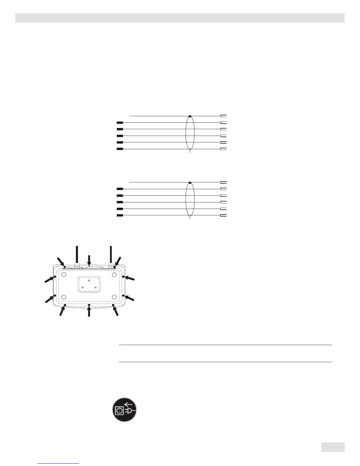
Cable Diagrams
Pin assignments for the cable from the indicator to an RS-232 PC interface (COM1).
Indicator side PC side
Models CAW1P, CAW2P DSUB connector
25-pin D-Sub male connector 9-pin or 25-pin
1
Sgn GND 7 5 GND 7 GND
TxD 2 2 RxD 3 RxD
RxD 3 3 TxD 2 TxD
DTR 20 8 CTS 5 CTS
CTS 5 4 DTR 20 DTR
Models CAW1S, CAW2S
Open cable end DSUB connector
9-pin or 25-pin
Sgn GND 15 5 GND 7 GND
TxD 14 2 RxD 3 RxD
RxD 13 3 TxD 2 TxD
DTR 12 8 CTS 5 CTS
CTS 11 4 DTR 20 DTR
Closing the Combics Indicator
t Re-attach the front panel and secure it with the ten cap nuts ( 1Nm ).
Connecting the Device to AC Power
The indicator is powered through the pre-installed power cord. The power supply is
integrated into the indicator. The device can be operated with a supply voltage of
100 V to 240 V.
3
The power connection must be made in accordance with the regulations applicable
in your country.
Make sure that the voltage rating printed on the manufacturer's ID label is identical
to that of your local line voltage. If the voltage specifi ed on the label or the plug
design of the AC adapter do not match the rating or standard you use, please
contact your Sartorius offi ce or dealer.
t Check the voltage rating and plug design.
t The device must be plugged into a properly installed wall outlet.
Getting Started
 Loading...