Operating Instructions Combics Indicators 7
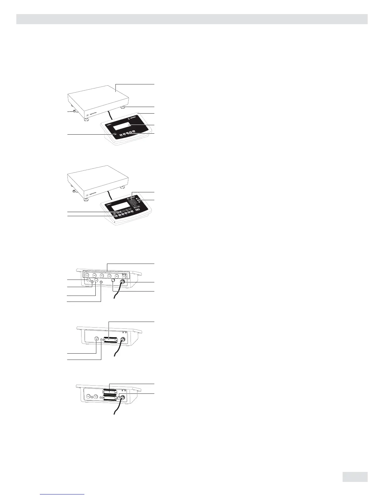
General View of the Equipment
Combics 1 and 2
1 Level indicator
2 Load plate
3 Leveling feet
4 Indicator
5 Display (for a detailed diagram, please see the chapter
“Operating Design”)
6 General Function Keys: Zero, Tare, Switch function, Adjustment/
Calibration, Print/Data output
(see “Operating Design”)
7 On/Off Key
Combics 2 only
8 10 digit keypad for entering values
9 LEDs
(for checkweighing and classification)
10 Additional function keys (see “Operating Design”)
11 Toggle between weighing platforms (WP)
Rear view of indicator:
8 Connection options for
– COM 1 standard
– 2nd UNICOM interface for additional, optional functions
(e. g. Ethernet, profi bus, etc.)
– CAW2S: a barcode scanner can be connected via a terminal
block
9 Power cord with country-specific plug
10 Vent valve: 1.5 Nm
11 Weighing platform WP 1 and/or WP 2 connection
12 Input for menu access switch (standard or legal-for-trade mode)
for WP 1 and/or WP 2
13 RS-232C interface “COM 1” (standard equipment)
14 Second “UNICOM” interface (Combics 2 only)
15 Combics 2 only: PS/2 connection (barcode scanner, external
keypad)
Device Description
13
9
10
8
14
15
12
11
12
11
12
11
CAW1S | CAW2S | CAH1
CAW1P
CAW2P
2
3
1
4
5
7
6
8
10
9
11
 Loading...