EasyManuals Logo

Sartorius Cubis Series Operating Instructions

Sartorius Cubis Series
121 pages
To Next Page IconTo Next Page
To Previous Page IconTo Previous Page
Page #67 background imageLoading...
Page #67 background image
Cubis MSE Operating Instructions 67
Data Interfaces
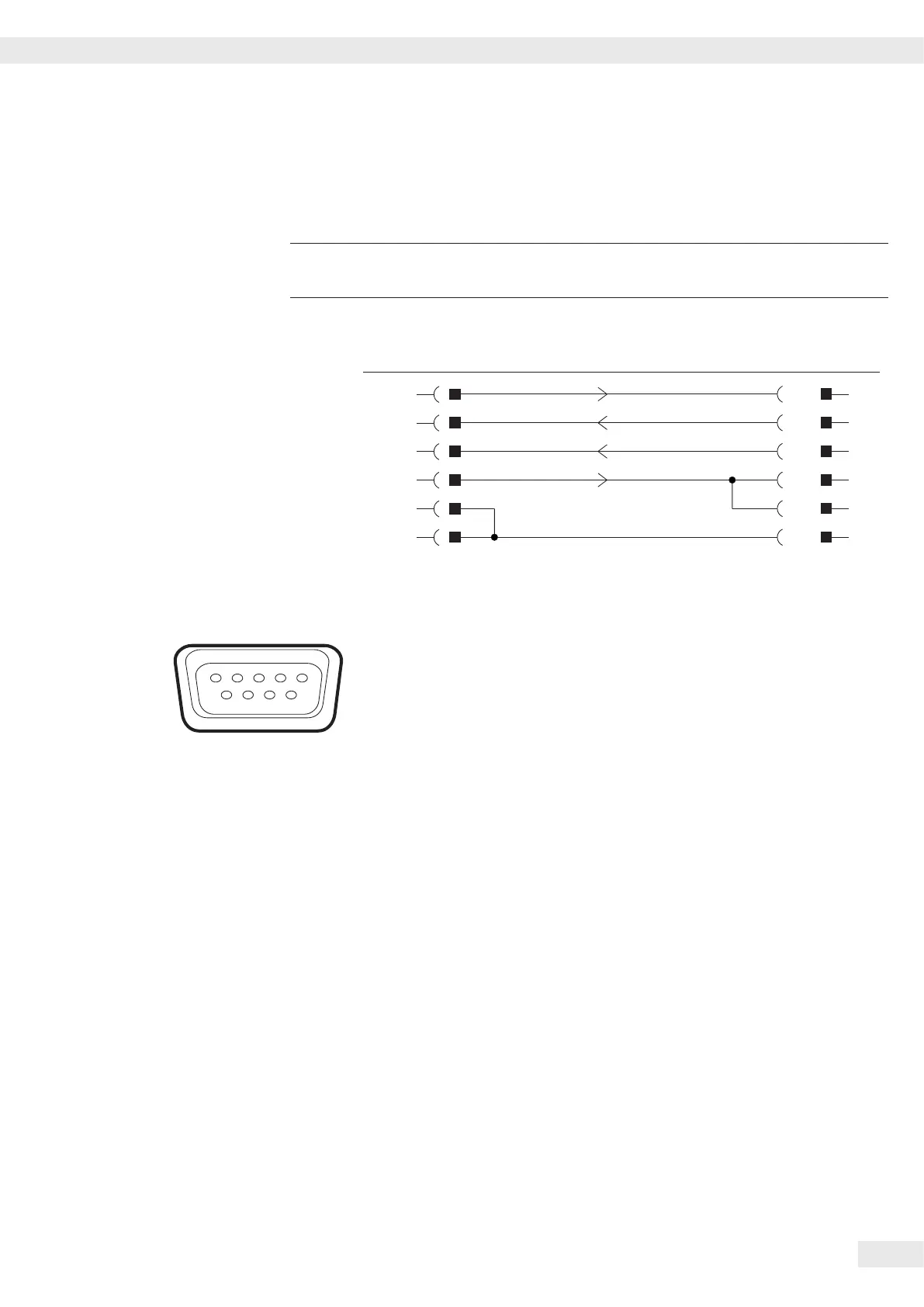
Cabling Diagram 25-pin Interface
Diagram for interfacing a computer or other peripheral device to the balance using
the RS-232/V24 standard and cables up to 15 m (50 ft�) long
3
Do not connect any other pins to the cable connector of the balance.
W
aage Computer
Stecker Buchse
25-pin 9 pin
TxD 2 2 RxD
RxD 3 3 TxD
CTS 5 4 DTR
DTR 20 8 CTS
GND 4/7 6 DSR
GND 14 5 GND
Cable type: AWG 2 specification
Pin Assignment Chart, 9-contact Female Connector, RS-232:
Pin 1: Not used
Pin 2: Data output (TxD)
Pin 3: Data input (RxD)
Pin 4: Not used
Pin 5: Internal ground (GND)
Pin 6: Not used
Pin 7: Clear to send (CTS)
Pin 8: Data Terminal Ready (DTR)
Pin 9: Not used
Establish a connection via a conventional RS-232 cable�
Balance
Plug
25-pin
Computer
socket
9-pin

Other manuals for Sartorius Cubis Series

Questions and Answers:

Question and Answer IconNeed help?

Do you have a question about the Sartorius Cubis Series and is the answer not in the manual?

Sartorius Cubis Series Specifications

General IconGeneral
DisplayColor touch screen
Readability0.01 mg to 1 g
InterfacesUSB, Ethernet, RS-232
CalibrationInternal and external
HousingDie-cast aluminum
Response TimeVaries by model
Pan SizeVaries by model
Operating Temperature10°C to 30°C
ComplianceGLP
Power Supply100 – 240 V, 50/60 Hz
CapacityVaries by model (up to 64 kg)
RepeatabilityVaries by model
LinearityVaries by model

Related product manuals