Operating the Scale
107
Cabling Diagram (adapter cable
– round – DB25-scale)
Order No. YCC01-0016M3
Female interface connector:
25-contact, D-Submini DB25S with
screw lock hardware
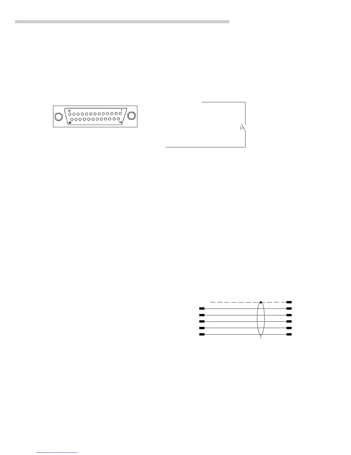
Pin labeling of the 25-contact D-SUB
connector:
Connector – front view
Male connector used:
(please use connectors with the
same specifications):
25-pin D-Submini DB25S, with
integrated shielded cable clamp
assembly (Amp type 826 985-1C)
and fastening screws (Amp type
164 868-1)
Pin Assignment:
Pin 1: Signal Ground
Pin 2: Data Output (TxD)
Pin 3: Data Input (RxD)
Pin 4: Signal Return (TxD/RxD)
Pin 5: Clear to Send (CTS)
Pin 6: Internally Connected
Pin 7: Internal Ground
Pin 8: Internal Ground
Pin 9: Reset _ In**)
Pin 10: –12 V
Pin 11: +12 V
Pin 12: Reset _ Out**)
Pin 13: +5 V
Pin 14: Internal Ground
Pin 15:
Pin 16: <
Pin 17: =
Pin 18: >
Pin 19: SET
Pin 20: Data Terminal Ready (DTR)
Pin 21: Supply Voltage Ground “COM”
Pin 22: Not Connected
Pin 23: Not Connected
Pin 24: Supply Voltage Input +15…25 V
Pin 25: +5 V
Cabling Diagram (Adapter Cable for PC)
(Adapter cable YCC01-03ISM5 – round – DB25-PC)
– Diagram for interfacing a computer to the scale using the RS-232C/V24
standard and cables up to 15 m (50 ft) long
Cabling diagram:
Connection assignments for the cable from the scale to an
RS-232 PC interface
Round connector or, 25-contact
12-pin D-Submini
connector
Shield 1
Sgn GNDE 7
Scale TxD B 3
side RxD C 2 PC side
DTR D 5
CTS H 20
(The other pins are Shield on
not connected) both sides
 Loading...